You are designing a new extension, replacing every window in your home, or specifying ventilation for a block of flats. At some point, someone mentions "Part F" and hands you a 60-plus-page PDF. Where do you even start?
Building regulations Part F ventilation is the section of the Building Regulations 2010 (Schedule 1, Part F) that sets the minimum ventilation standards for buildings in England. Its purpose is to ensure adequate means of ventilation are provided to maintain indoor air quality by controlling moisture, pollutants, and stale air. Approved Document F is the government-published guidance showing how to comply with these legal requirements.
That distinction matters more than most summaries let on. The Regulation itself — Part F of Schedule 1 — is the legal requirement. Approved Document F is the practical guidance the government publishes to help you meet that requirement. You are not legally obliged to follow Approved Document F to the letter, but if you do, it is generally accepted as evidence of compliance. Deviate from it, and you will need to demonstrate through other means that your design still satisfies the Regulation.
Part F sits within the Building Regulations 2010, the statutory instrument governing building work in England. Its core obligation is straightforward: provide adequate ventilation so that the health of occupants is not put at risk by poor indoor air quality. In practice, that means controlling condensation in bathrooms and kitchens, diluting pollutants generated by cooking and cleaning, and ensuring a steady supply of fresh air throughout every habitable space.
Enforcement falls to Building Control — either a local authority building control team or an approved inspector. They check ventilation strategies at the design stage, inspect installations on site, and may request commissioning data before issuing a completion certificate. Ignoring these requirements can lead to prosecution, unlimited fines, and enforced rectification of non-compliant work for up to two years after completion.
Since April 2023, the Building Safety Regulator — established under the Building Safety Act 2022 — also holds a duty to keep building safety and standards under review across England, which includes advising government on updates to the Approved Documents. So the regulatory landscape is actively evolving.
Approved Document F is split into two volumes, and identifying which one applies to your project is the essential first step. Volume 1 covers dwellings — houses, flats, modular homes, and conversions to residential use. Volume 2 covers buildings other than dwellings — offices, schools, retail premises, hospitals, and similar non-domestic buildings. The table below highlights the key differences.
| Volume 1: Dwellings | Volume 2: Buildings Other Than Dwellings | |
|---|---|---|
| Scope | Houses, flats, modular dwellings, dwelling conversions | Offices, schools, retail, hospitals, hotels, leisure facilities |
| Ventilation approach | Four defined system strategies (Systems 1-4) with prescriptive airflow rates per room type | Performance-based targets; CO2 monitoring now required in many occupiable rooms for new builds |
| Key metric | Minimum extract rates in litres per second by room; whole-dwelling ventilation rate by number of bedrooms | Fresh air supply per person per second or per square metre of floor area, whichever is higher |
| Primary audience | Architects, housebuilders, window installers, self-builders, homeowners | M&E engineers, commercial developers, facility managers, sustainability officers |
| Document length | 62 pages (2022 edition) | 48 pages (2022 edition) |
This article focuses primarily on Volume 1 — the dwelling-specific requirements that affect the widest range of construction professionals and homeowners in England. Where Volume 2 diverges in important ways, we will flag it.
Think of what follows as a bridge between those dense official PDFs and the oversimplified summaries you have probably already found online. Whether you are an architect specifying a whole-house ventilation strategy, a contractor installing extract fans, or a homeowner trying to understand why your new windows need trickle vents, the goal is the same: give you the specific rates, system options, and compliance details that most guides leave out.
And the place to begin is with the three distinct types of ventilation that Part F recognises — each serving a different purpose, yet all required to work together as a single, coherent strategy.
Imagine a kitchen full of steam from a boiling pot, a living room with stale air that has not been refreshed in hours, and a bedroom freshly coated in paint fumes. Each of those scenarios demands a different ventilation response — different in speed, different in method, and different in purpose. That is exactly why the building regulations ventilation Part F framework does not rely on a single type of ventilation. It requires three, working together as a complete strategy.
Every compliant dwelling in England needs all three of these ventilation types addressed. Miss one, and the whole strategy falls apart — even if the other two are perfectly installed. Here is how each one works and why it matters.
Extract ventilation is the frontline defence against condensation. Its job is to remove moist or polluted air directly at the source, before it has a chance to migrate through the rest of the dwelling. You will find extract ventilation in what Approved Document F calls "wet rooms" — kitchens, bathrooms, utility rooms, and WCs. These are the spaces where moisture and pollutants are generated most intensely, whether from cooking, bathing, or running a tumble dryer.
There are two approaches to extract ventilation, and the choice depends on which of the four system strategies a dwelling uses:
Both approaches share the same goal: capture moisture-laden or pollutant-heavy air before it condenses on cold surfaces or degrades indoor air quality elsewhere in the home. Without effective extract ventilation, condensation leads to mould growth — a health risk that Part F building regulations ventilation standards are specifically designed to prevent.
Extract ventilation pulls air out. But where does replacement air come from? That is the role of background ventilation — a continuous, controllable trickle of fresh outdoor air into habitable rooms and wet rooms alike. Think of it as the dwelling's breathing mechanism: quiet, constant, and easy to overlook, yet essential for preventing the slow accumulation of indoor pollutants over hours and days.
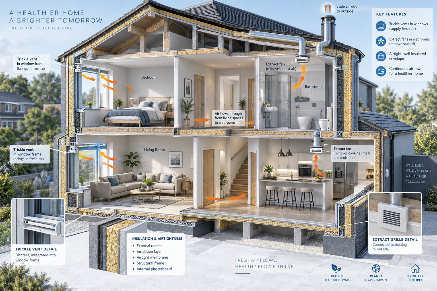
In most dwellings, background ventilation is achieved through trickle vents — small, slotted ventilators integrated into window frames or mounted directly on the wall above a window. These are not designed to create a noticeable draught. Instead, they provide a controlled minimum air supply that dilutes pollutants generated by everyday activities: off-gassing from furniture, volatile organic compounds from cleaning products, carbon dioxide from occupants, and moisture from simply being at home.
As noted in the Approved Document F Volume 1 FAQs, background ventilators can also be installed through a wall rather than within a window frame, provided they deliver the required equivalent area. A night-latch position on a window, however, is explicitly not an acceptable substitute — it does not offer a sufficiently secure means of background ventilation. This distinction catches many homeowners and even some installers off guard.
The key point is that background ventilation operates independently of occupant behaviour. Extract fans rely on someone using a kitchen or bathroom. Purge ventilation relies on someone opening a window. Background ventilators, by contrast, should remain open at all times to maintain a baseline level of air quality throughout the dwelling.
Sometimes, neither steady trickle ventilation nor localised extraction is enough. After painting a room, dealing with a chemical spill, or clearing smoke from a cooking incident, you need the ability to flush the entire air volume of a room quickly. That is purge ventilation — a rapid, high-volume air exchange designed to dilute unusually high concentrations of pollutants in a short time.
Purge ventilation is typically achieved through openable windows. The general requirement in Approved Document F Volume 1 is that the openable area of the window (or combination of windows) should be at least one-twentieth of the floor area of the room served. So a 20 m² bedroom would need at least 1 m² of openable window area for purge ventilation purposes.
Unlike extract and background ventilation, purge ventilation is not continuous. It is an emergency or occasional measure — available when needed, but not part of the day-to-day ventilation strategy. Every habitable room and every wet room must have a means of purge ventilation, regardless of which mechanical or passive system the dwelling uses.
These three ventilation types are not alternatives to one another. They are layers in a single, integrated strategy. Here is a quick-reference summary:
A dwelling that has excellent extract fans but no trickle vents will develop negative pressure problems and stale air in rooms away from the fans. A dwelling with generous trickle vents but no extract in the bathroom will still grow mould on the ceiling. And a dwelling with no openable windows — regardless of how sophisticated its mechanical system is — will fail the purge ventilation requirement.
Getting all three right is the starting point. The next question is how they are combined into a practical, installable system — and that is where Part F's four ventilation system strategies come in, each assembling these three types in a different configuration suited to different building types and airtightness levels.
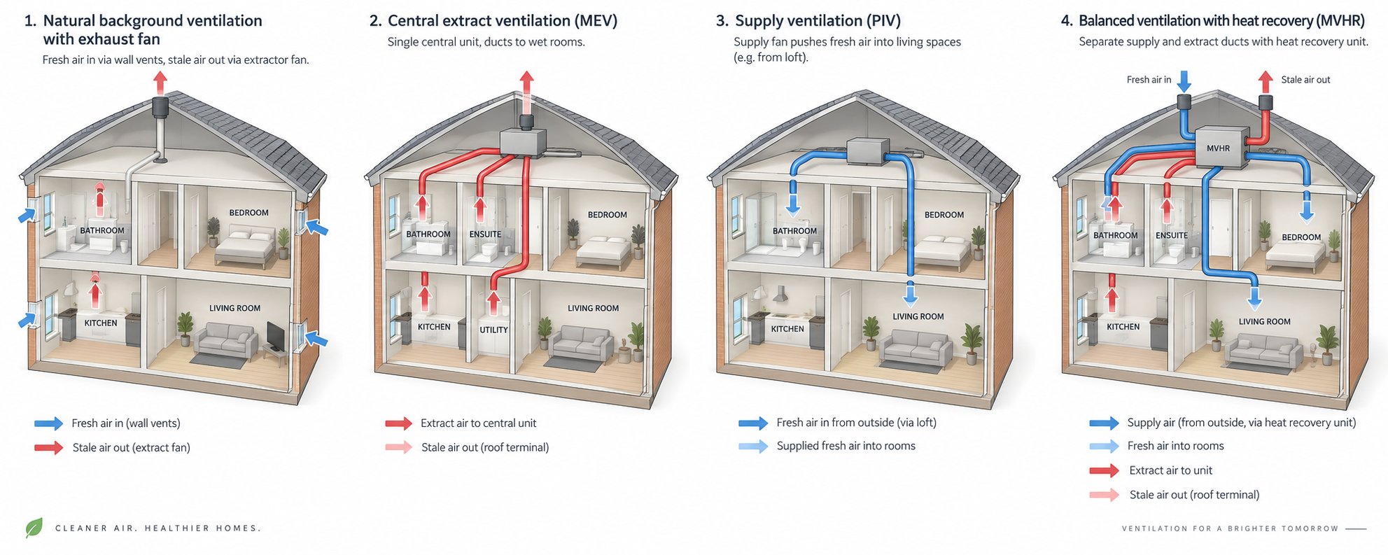
Knowing that you need extract, background, and purge ventilation is one thing. Deciding how to deliver all three in a real building is something else entirely. Approved Document F Volume 1 does not leave that decision to guesswork. It defines four distinct system strategies — numbered simply System 1 through System 4 — each combining the three ventilation types in a different configuration. Your job as a designer, specifier, or contractor is to select the strategy that best fits the dwelling's construction type, airtightness level, energy targets, and budget.
Most guides mention these systems in passing. Few explain what each one actually requires you to install, where each one works best, or how airtightness should influence your choice. Here is the full breakdown, drawn from the UK building regulations Part F ventilation requirements for dwellings.
This is the most widely used approach in traditional UK housing. System 1 relies entirely on passive air supply combined with mechanical extraction only when and where it is needed.
The components are straightforward. Every habitable room — living rooms, dining rooms, bedrooms — receives a background ventilator, typically a trickle vent in the window frame. Every wet room — kitchens, bathrooms, utility rooms, WCs — also receives a background ventilator plus an intermittent extract fan. These fans are triggered by occupant activity (a pull cord, a light switch, or a humidistat) and run at a prescribed minimum extraction rate for the room type.
Fresh air enters through the background ventilators under natural pressure differences created by wind and the stack effect. Stale, moist air exits through the extract fans. Purge ventilation is provided by openable windows in every room.
System 1 suits dwellings with relatively conventional construction and moderate airtightness. In buildings that are quite leaky — say, older masonry homes with air permeability well above 5 m³/h/m² at 50 Pa — uncontrolled infiltration through gaps in the fabric provides additional, incidental ventilation. But as construction standards tighten and buildings become more airtight, System 1 reaches its limits. When there is not enough natural pressure difference to draw air through the trickle vents reliably, you need a system with mechanical assistance on the supply side, the extract side, or both.
System 2 takes the extract function and makes it continuous rather than intermittent. A centralised or decentralised mechanical extract ventilation (MEV) unit runs constantly at a low background rate, drawing air out of all wet rooms through ducted connections or individual room fans. When a kitchen or bathroom is in active use, the extract rate boosts to a higher level — either automatically via sensors or manually by the occupant.
Fresh air still enters through background ventilators in every habitable room, just as in System 1. The difference is that the constant mechanical extraction creates a slight negative pressure inside the dwelling, which actively pulls outdoor air through the trickle vents rather than relying solely on wind and stack effect. This makes System 2 more reliable in calm weather conditions and in dwellings with moderate-to-good airtightness.
MEV systems are popular in apartments and social housing developments, where centralised duct runs can serve multiple wet rooms efficiently. Decentralised variants — individual continuously running fans in each wet room — offer a simpler retrofit option where routing ductwork to a central unit is impractical.
System 3 flips the mechanical emphasis. Instead of extracting air mechanically and relying on passive supply, a central supply fan actively delivers filtered, and sometimes tempered, fresh air to habitable rooms through a duct network. Wet rooms still use intermittent extract fans to remove moisture and pollutants at source, just as in System 1.
The advantage? The incoming air can be filtered to remove pollen, particulates, and outdoor pollutants before it reaches living spaces — a meaningful benefit in urban locations or areas near busy roads. The supply air can also be warmed slightly using a small heater coil, reducing cold draughts that sometimes discourage occupants from leaving trickle vents open in winter.
System 3 is less common in mainstream UK housebuilding than Systems 1, 2, or 4. It occupies a middle ground: more controlled than natural ventilation, but without the heat recovery efficiency of a full MVHR system. You will most often encounter it in developments where filtered air supply is a priority but the budget or building layout does not support a fully ducted balanced system.
System 4 is the most engineered — and increasingly the most specified — approach for new-build dwellings targeting high energy performance. An MVHR unit provides both supply and extract through a balanced, ducted system. Fresh outdoor air is drawn in, passed through a heat exchanger that recovers warmth from the outgoing stale air, and then distributed to habitable rooms. Simultaneously, moist or polluted air is continuously extracted from wet rooms, passes through the other side of the heat exchanger, and is exhausted outside.
Heat recovery efficiencies of 90% or more are achievable with well-installed units, making MVHR the natural partner for airtight construction where uncontrolled heat loss through gaps in the building fabric has been minimised. In fact, MVHR only delivers its intended energy benefit when the dwelling is sufficiently airtight — typically below 3 m³/h/m² at 50 Pa. In leakier buildings, the unit works against uncontrolled infiltration and the energy savings disappear.
Because MVHR handles both supply and extract mechanically, background ventilators (trickle vents) are generally not required — the ducted supply takes their place. Purge ventilation through openable windows is still needed, however, as mechanical systems alone may not achieve the rapid air-change rate needed during high-pollution events. Careful design of the duct layout, proper commissioning, and regular filter maintenance are all critical to System 4 performing as intended.
Choosing between these strategies involves weighing construction type, airtightness targets, cost constraints, and long-term energy goals. The table below puts the key differences side by side — a reference tool you can return to at the specification stage.
| System 1: Natural + Intermittent Extract | System 2: Continuous MEV | System 3: Continuous Supply + Intermittent Extract | System 4: MVHR | |
|---|---|---|---|---|
| Components required | Background ventilators (trickle vents) in all rooms; intermittent extract fans in wet rooms; openable windows | Background ventilators in habitable rooms; central or decentralised MEV unit continuously extracting from wet rooms; openable windows | Central supply fan with duct network to habitable rooms; intermittent extract fans in wet rooms; openable windows | MVHR unit with ducted supply to habitable rooms and ducted extract from wet rooms; heat exchanger; filters; openable windows for purge |
| Typical building suitability | Traditional masonry construction; houses with moderate airtightness | Apartments, social housing, mid-airtightness new builds | Urban or roadside locations where filtered supply is beneficial; moderate airtightness | High-performance new builds targeting low energy use; airtight construction |
| Advantages | Lowest capital cost; simple to install and maintain; no ductwork needed | More reliable extraction than intermittent fans; works well in calm weather; lower running cost than MVHR | Filtered incoming air; reduced cold draughts; positive pressure can limit ingress of outdoor pollutants | Recovers up to 90%+ of heat from exhaust air; best indoor air quality control; essential for Passivhaus and Future Homes Standard targets |
| Disadvantages | Reliant on wind and stack effect for air supply; less effective in very airtight buildings; no heat recovery | Still relies on passive air supply through trickle vents; no heat recovery; ductwork needed for centralised MEV | Less common, so fewer installer specialists; no heat recovery on supply side; requires ductwork | Highest capital and installation cost; requires careful duct design and sealing; needs regular filter changes; only efficient in airtight buildings |
| Indicative airtightness suitability | Above 5 m³/h/m² at 50 Pa (leaky to moderate) | 3 to 5 m³/h/m² at 50 Pa (moderate) | 3 to 5 m³/h/m² at 50 Pa (moderate) | Below 3 m³/h/m² at 50 Pa (airtight) |
A few points worth flagging. The airtightness thresholds above are indicative, not regulatory hard lines — Approved Document F does not mandate a specific system at a specific airtightness level. Instead, it expects the designer to select a strategy that will deliver adequate ventilation given the actual air permeability of the dwelling. In practice, Building Control will scrutinise a System 1 proposal for a dwelling designed below 3 m³/h/m² at 50 Pa, because relying on passive air supply in a very tight envelope is unlikely to deliver the required whole-dwelling ventilation rate.
The Future Homes Standard, expected to take full effect by 2025, pushes new dwellings toward significantly lower carbon emissions and tighter fabric performance. That trajectory makes System 4 (MVHR) increasingly dominant in new-build specification. But for extensions, refurbishments, and window replacements — the projects that make up the bulk of UK building work — Systems 1 and 2 remain by far the most commonly encountered.
Selecting a system is only half the task, though. Each strategy carries specific minimum airflow rates that must be met at each extract point and across the dwelling as a whole — and those rates are the numbers most guides never actually publish.
Every system strategy described above is only as good as the numbers behind it. You can select the right system, install the right components, and position fans in the right rooms — but if the airflow rates fall short of the prescribed minimums, Building Control will reject the installation. These rates, specified in approved document F airflow rates litres per second, are the compliance backbone that separates a ventilation strategy on paper from one that actually protects indoor air quality.
Surprisingly, most online summaries of Part F skip these figures entirely. Yet they are exactly what installers need when sizing a fan, what architects need when writing a specification, and what Building Control officers check during commissioning. Here they are.
Approved Document F Volume 1 sets out part f minimum extract ventilation rates for each wet room type, broken into two categories: the intermittent rate (for System 1 and System 3, where fans run on demand) and the continuous rate (for System 2 MEV and System 4 MVHR, where fans run constantly and boost when needed). The table below consolidates these figures directly from the Approved Document F Volume 1 tables.
| Room Type | Minimum Intermittent Extract Rate (l/s) | Minimum Continuous Extract Rate — Boost (l/s) |
|---|---|---|
| Kitchen (cooker hood adjacent to hob) | 30 | 13 |
| Kitchen (extract fan elsewhere in room) | 60 | 13 |
| Utility room | 30 | 8 |
| Bathroom | 15 | 8 |
| WC (toilet only) | 6 | 6 |
A few things to notice. A kitchen extract fan that is not positioned directly above the hob must deliver double the rate — 60 l/s instead of 30 l/s — because it cannot capture cooking moisture and grease as efficiently from a remote location. This single detail accounts for a significant number of failed commissioning tests. If you are specifying a ceiling-mounted fan rather than a cooker hood, you need a considerably more powerful unit.
For continuous systems (Systems 2 and 4), the boost rates in the right-hand column apply when the room is in active use. At all other times, the system runs at a lower background rate. That lower rate is not a fixed figure per room — instead, it is tied to the whole-dwelling ventilation rate, which brings us to the next critical set of numbers.
Extract rates handle individual rooms. But Part F also requires a minimum rate of fresh air supply for the entire dwelling, calculated primarily from the number of bedrooms — which the regulations use as a proxy for assumed occupancy. The whole-dwelling ventilation rate is the total volume of air, in litres per second, that must flow through the home continuously to maintain acceptable indoor air quality.
The 2022 edition of Approved Document F Volume 1 increased these whole-dwelling rates compared to the previous 2013 edition, reflecting the push toward better indoor air quality in increasingly airtight homes. The updated whole-dwelling rates are notably higher, meaning ventilation systems designed to the old figures may no longer comply.
The general framework works as follows:
For continuous mechanical systems (Systems 2 and 4), the sum of all continuous low-rate extract flows from every wet room must at least equal this whole-dwelling rate. If it does not, the system is undersized — even if every individual room hits its boost target. This is a common design error: sizing each room's fan correctly in isolation but failing to check the aggregate against the whole-dwelling minimum.
For Systems 1 and 2, where fresh air enters through background ventilators rather than mechanical supply, Part F specifies minimum equivalent areas for trickle vents in each room. Equivalent area is not the physical opening size of the ventilator — it is the aerodynamically effective open area, measured in square millimetres (mm²), that accounts for the resistance of grilles, baffles, and filters. Manufacturers test and declare equivalent area values for their products, so you can compare directly against the Part F requirements.
The 2022 edition made a significant change here. Under the previous 2013 guidance, minimum ventilator areas were calculated on a whole-dwelling basis depending on total floor area and bedroom count. The current edition moves to a room-by-room basis, specifying minimum equivalent areas for each individual room. For example, bedrooms require a minimum equivalent area of 8,000 mm² per room for background ventilators.
For dwellings using continuous mechanical extract (System 2), the minimum equivalent area for background ventilators in each habitable room was increased from 2,500 mm² under the 2013 document to 4,000 mm² under the current edition. That is a 60% increase — a change that directly affects trickle vent sizing and, by extension, window frame specification.
Here is why this matters in practice. If you are specifying replacement windows for a dwelling that relies on System 1 or System 2 ventilation, each window must accommodate a trickle vent with at least the minimum equivalent area for that room type. Choosing a vent that falls short — even by a few hundred square millimetres — means the dwelling fails the part f equivalent area requirements trickle vents mandate, and Building Control will not sign it off.
These numbers — extract rates per room, whole-dwelling ventilation rates per bedroom count, and equivalent areas per room — are the quantitative foundation of every Part F compliance assessment. With them in hand, the next practical question is which of these requirements actually apply to your specific project, because Part F does not treat all building work the same way.

A homeowner replacing three windows faces a completely different set of Part F obligations than an architect designing a 200-unit residential development from scratch. Yet most ventilation guidance treats every project as though it were a new build, burying the distinctions — or ignoring them altogether. The reality is that your compliance burden under building regulations Part F ventilation depends almost entirely on the type of building work you are undertaking.
Getting this wrong is costly. Overspecify, and you waste money on ventilation provisions the regulations do not require. Underspecify — or assume the rules do not apply — and you face a Building Control rejection, remedial work, and potential enforcement action. Here is how Part F obligations break down across the four most common project types.
New builds carry the heaviest compliance load. Every new dwelling must satisfy Part F in full, which means selecting and installing one of the four ventilation system strategies (Systems 1 through 4), providing the correct minimum extract rates in every wet room, achieving the whole-dwelling ventilation rate for the bedroom count and floor area, ensuring adequate background ventilation through correctly sized trickle vents or mechanical supply, and including purge ventilation in every habitable room and wet room.
There is no partial compliance route for new construction. Building Control expects a complete ventilation strategy submitted at design stage, verified during site inspections, and formally commissioned before a completion certificate is issued. For building regulations Part F new build ventilation compliance, the commissioning step is non-negotiable — mechanical systems must demonstrate they hit their prescribed airflow rates at every terminal.
With the Future Homes Standard driving new-build construction toward progressively tighter building envelopes, the vast majority of new dwellings are now specified with System 2 (MEV) or System 4 (MVHR). System 1 remains viable for some traditional masonry projects, but Building Control will scrutinise any natural ventilation proposal for a dwelling designed below 5 m³/h/m² at 50 Pa.
Extensions occupy a middle ground that confuses many homeowners and contractors alike. You are not building a new dwelling, so do the full Part F requirements still apply?
The answer is nuanced. An extension must provide adequate ventilation to the new space itself — meaning extract ventilation in any new wet rooms, background ventilation in new habitable rooms, and purge ventilation through openable windows. The specific rates and equivalent areas from Part F apply to the new rooms just as they would in a new build.
Critically, though, the extension must also not make ventilation in the existing dwelling worse than it was before the work started. This is the principle that catches people out. Imagine you are building a rear kitchen extension that removes an external wall containing a window with a trickle vent. That vent provided background ventilation to the original kitchen. By removing it, you have reduced the dwelling's ventilation provision — and you must compensate, either by installing a new background ventilator in the extension or by reconfiguring the ventilation strategy for the affected rooms.
Material alterations — structural changes to load-bearing elements, for example — trigger Part F obligations for the areas affected by the work. If you are knocking through walls to create an open-plan living space, the resulting combined room may need its own extract or background ventilation reassessed to account for the changed layout and volume.
Part F ventilation requirements for extensions boil down to a simple two-part test: ventilate the new space properly, and leave the existing dwelling no worse off.
This is where the regulations affect the widest audience — and where compliance failures are most common. Replacing windows or external doors in an existing dwelling is classified as work on a controlled fitting. While the thermal performance of the replacement is governed by Part L, the ventilation implications fall squarely under Part F.
The core rule is straightforward: the replacement must provide ventilation that is at least as good as what was there before. In practice, that means:
Part F ventilation window replacement regulations trip up installers and homeowners more than almost any other aspect of the document. The reason is simple: many people do not realise that swapping windows triggers a ventilation obligation at all. They see it as a like-for-like replacement. The regulations see it as an opportunity to maintain — or improve — the dwelling's air quality provisions.
Converting a non-residential building into a dwelling — an office-to-residential conversion, a barn conversion, a shop-to-flat scheme — triggers full Part F compliance appropriate to the new residential use. The building may never have needed domestic-grade ventilation before, but the moment it becomes a dwelling, it must meet every requirement that a new-build dwelling would face: a complete ventilation strategy, correct extract and background rates, and purge ventilation in every habitable room and wet room.
Part F ventilation change of use requirements are particularly demanding because these buildings often have existing fabric that was never designed with domestic ventilation in mind. Deep window reveals may limit trickle vent placement. Thick masonry walls may require wall-mounted background ventilators instead. Existing mechanical systems designed for commercial occupancy patterns — intermittent office hours rather than 24-hour residential use — rarely meet the continuous ventilation rates Part F demands for dwellings.
The practical lesson? Budget for a full ventilation design from the earliest feasibility stage, not as an afterthought once the planning permission is secured.
Identifying which category your project falls into is the first step toward a compliant ventilation design. But compliance does not exist in isolation. Part F shares the regulatory stage with Part L (energy efficiency) and Part O (overheating), and the interplay between these three documents creates design tensions that every specifier needs to resolve — particularly as airtightness targets continue to tighten.
Part F does not operate in a vacuum. It shares the regulatory stage with Part L (conservation of fuel and power) and Part O (overheating), and the demands these three documents place on a building sometimes pull in opposite directions. Seal the envelope tighter to satisfy Part L, and you intensify the dwelling's dependence on designed ventilation under Part F. Open up windows to address Part O overheating, and you may breach acoustic limits in a noisy urban location. Resolving these tensions is one of the most important — and least discussed — practical challenges in modern residential construction.
Part L exists to reduce energy waste. Its trajectory over successive editions has been consistent: drive the building envelope tighter, minimise uncontrolled heat loss, and push carbon emissions down. The result is that new dwellings are built to dramatically lower air permeability levels than the housing stock of even 15 years ago. That is a win for energy efficiency — but it creates a direct consequence for ventilation.
In a leaky older home, gaps around windows, poorly sealed loft hatches, and cracks in brickwork provided a crude but real form of incidental ventilation. Air found its way in and out whether anyone planned for it or not. Indoor air quality was far from perfect, but moisture had somewhere to go and pollutants were diluted almost by accident. Part F requirements in those buildings could be met relatively simply — a few trickle vents and intermittent extract fans in wet rooms were usually enough.
Tighten the envelope below approximately 5 m³/h/m² at 50 Pa, and that incidental airflow drops sharply. Tighten it further — below 3 m³/h/m², where the Future Homes Standard is pushing new-build construction — and uncontrolled infiltration is virtually eliminated. Fresh air no longer arrives on its own. Every litre per second of ventilation must be deliberately designed, mechanically delivered, and properly commissioned. This is the airtightness paradox: the better you build for Part L, the harder you must work for Part F.
In practice, this means airtight buildings ventilation strategy Part F compliance almost always requires System 3 (continuous mechanical supply with intermittent extract) or System 4 (MVHR). System 1 — natural ventilation with intermittent extract fans — simply cannot guarantee the required whole-dwelling ventilation rate when there is not enough natural pressure difference to push air through trickle vents reliably. As EnviroVent's compliance guidance highlights, the risk of poor indoor air quality increases in proportion to airtightness, making mechanical ventilation systems essential for maintaining healthy air exchange in modern homes.
Designers have two routes to demonstrate compliance with this building regulations Part F Part L interaction:
Most projects default to the prescriptive route because it is quicker, cheaper, and less likely to trigger queries from Building Control. The performance route is typically reserved for complex or non-standard designs where strict adherence to the tables is impractical — for example, heritage conversions where installing standard trickle vents would compromise the listed facade.
Part O, introduced in June 2022, addresses a problem that was largely ignored by earlier editions of the Building Regulations: the risk of overheating in new residential buildings. As insulation levels have risen and glazing ratios have grown, summertime temperatures inside well-sealed dwellings can reach dangerous levels — particularly in south- and west-facing rooms, upper-floor apartments, and buildings in urban heat islands.
Part O applies to all new residential buildings in England. It does not apply to extensions, conservatories added after the building is complete, or buildings undergoing a change of use. For new builds, though, its requirements must be met alongside Part F and Part L from the outset.
Here is where the ventilation connection becomes critical. One of Part O's primary mitigation strategies is purge ventilation — exactly the same mechanism that Part F requires for rapid air replacement during high-pollution events. Openable windows serve double duty: they provide Part F purge ventilation and Part O overheating mitigation simultaneously. The simplified method in Approved Document O prescribes minimum free areas for openable windows expressed as a percentage of room floor area, which aligns closely with Part F's requirement that purge ventilation openings should be at least one-twentieth of the room's floor area.
Sounds harmonious? In many cases it is. But a serious design tension emerges in acoustically sensitive locations — near busy roads, railway lines, flight paths, or industrial sites. Part O wants windows open to shed excess heat at night. Part F wants windows available for purge ventilation. Yet opening those windows may expose occupants to unacceptable noise levels, undermining sleep quality and potentially conflicting with planning conditions or acoustic design standards.
The Approved Document O FAQs acknowledge this conflict directly. Solutions that reduce noise while still allowing airflow — such as smaller window openings, acoustic louvres, or ventilation louvres that qualify as secure openings — are acceptable, but the corresponding reduction in equivalent area must be factored into the overheating assessment. In some scenarios, designers may need to demonstrate compliance using the dynamic thermal modelling method rather than the simplified method, modelling alternative ventilation pathways that satisfy Part O without relying on fully open windows.
For part f ventilation Part O overheating compliance, the practical takeaway is this: you cannot design the ventilation strategy in isolation. The openable window that satisfies purge ventilation under Part F, the overheating free area under Part O, the acoustic performance needed for the site, and the thermal performance demanded by Part L all converge on the same window opening. Resolving that convergence requires early coordination between the architect, the M&E engineer, the acoustic consultant, and the window specifier — ideally before the planning application is submitted, not after.
This regulatory interplay has a direct and tangible impact on component specification. Nowhere is that more obvious than in the selection of background ventilators — the trickle vents that must deliver equivalent area for Part F, control noise ingress for acoustic compliance, and integrate seamlessly into the window frames that also serve Part L and Part O objectives.
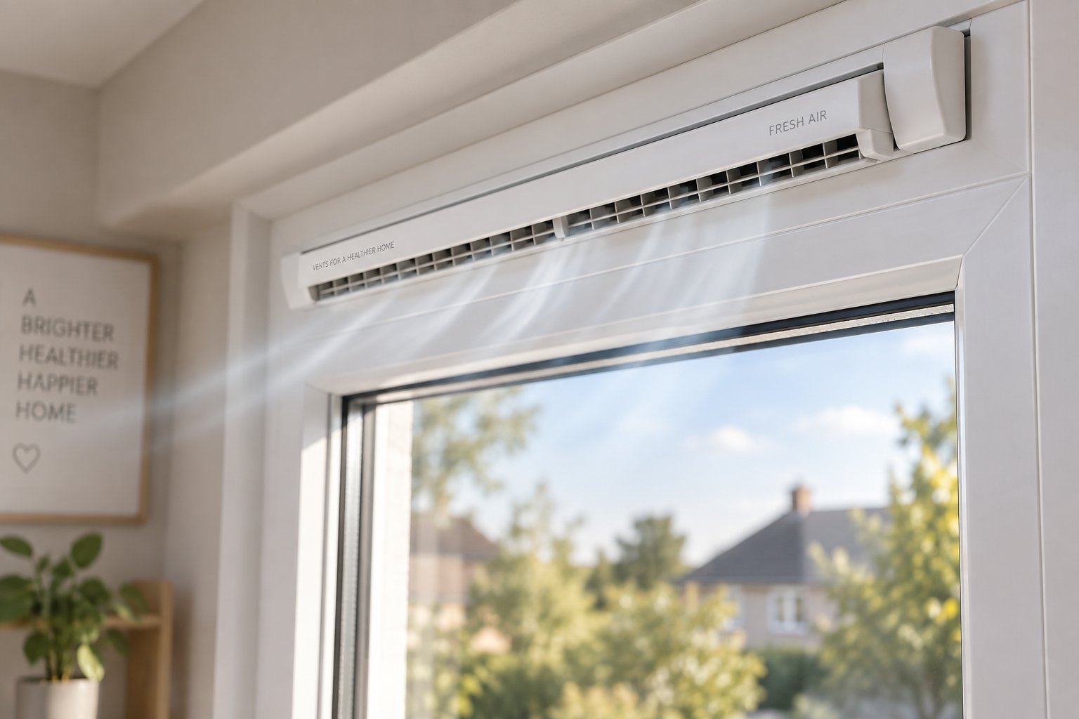
Trickle vents sit at the intersection of every regulatory tension discussed so far — airflow rates, equivalent area thresholds, acoustic performance, and frame integration. They are small components with outsized compliance consequences. Get the specification right, and Building Control sign-off is straightforward. Get it wrong — even slightly — and the entire background ventilation strategy for the dwelling fails.
For the majority of residential projects in England, trickle vents are the single most common Part F compliance touchpoint. Whether you are specifying windows for a new-build estate, an extension, or a batch of replacement units, understanding how these ventilators work within the regulatory framework is essential.
Two of the four ventilation system strategies — System 1 (natural ventilation with intermittent extract) and System 2 (continuous mechanical extract) — depend on background ventilators as the primary means of supplying fresh air to habitable rooms. In both systems, stale air is extracted mechanically from wet rooms, and replacement air enters through trickle vents installed in window frames or mounted on external walls. Without these ventilators, there is no designed pathway for fresh air to reach living rooms, bedrooms, studies, or dining rooms. The dwelling simply cannot meet its whole-dwelling ventilation rate.
Even in dwellings using System 2 (MEV), where the mechanical extract unit creates a slight negative pressure to actively draw air through the vents, the trickle vents themselves must still deliver the required equivalent area. The fan pulls; the vent supplies. Remove or undersize the vent, and the fan starves for make-up air — leading to increased infiltration through uncontrolled gaps, whistling around door frames, and reduced extract performance at the terminals.
The equivalent area figures from Approved Document F Volume 1 are non-negotiable. As covered in the airflow rates section above, habitable rooms require a minimum of 8,000 mm² equivalent area per room under the current 2022 edition, while wet rooms require 4,000 mm² per room in addition to their mechanical extract provision. These figures represent the aerodynamically effective open area of the ventilator — not its physical slot dimensions. A vent with a 4,000 mm² physical aperture may deliver only 3,200 mm² of equivalent area once internal baffles and grilles are accounted for. Always check the manufacturer's declared equivalent area, not the product's physical measurements.
Here is a practical example. A three-bedroom house using System 1 might have the following background ventilation requirement:
| Room | Minimum Equivalent Area (mm²) | Typical Vent Provision |
|---|---|---|
| Living room | 8,000 | 2 to 3 slot vents across one or more windows |
| Bedroom 1 | 8,000 | 2 to 3 slot vents |
| Bedroom 2 | 8,000 | 2 slot vents or 1 large-format vent |
| Bedroom 3 | 8,000 | 2 slot vents or 1 large-format vent |
| Kitchen | 4,000 + mechanical extract | 1 slot vent + extract fan or cooker hood |
| Bathroom | 4,000 + mechanical extract | 1 slot vent + extract fan |
The vents in each room can be distributed across multiple windows. A bay window with three openable lites, for instance, could carry one vent per lite — so long as the combined equivalent area across all three meets or exceeds the 8,000 mm² threshold for that habitable room. This flexibility is useful in rooms with several smaller windows rather than a single large unit.
Selecting a part f compliant trickle vent specification involves more than matching an equivalent area number. In acoustically sensitive locations — properties near busy roads, railway lines, airport flight paths, or mixed-use developments — the ventilator must also control sound transmission. This is where many specifications fall short: a standard slot vent that delivers 4,000 mm² equivalent area may let through enough traffic noise to make a bedroom uninhabitable at night, even with the window fully closed.
Acoustic trickle vents address this by incorporating internal baffles and sound-attenuating chambers that reduce noise transmission while still permitting airflow. Their performance is measured as Dn,e,w — the element-normalised level difference, expressed in decibels. A higher Dn,e,w value means better sound insulation. As Titon's acoustic testing guidance explains, credible performance data should come from independent, UKAS-accredited laboratories testing to the ISO 10140 series, not from manufacturer self-declarations alone.
There is a catch, however. Acoustic baffles increase resistance to airflow, which means an acoustic vent typically has a lower equivalent area than a standard vent of the same physical size. A standard 250 mm slot vent might deliver 4,000 mm² equivalent area; its acoustic counterpart, with internal baffles, might deliver only 2,500 mm² to 3,500 mm². That means you may need more acoustic vents per room to hit the Part F minimum — increasing cost, requiring more frame preparation, and potentially affecting the window's aesthetic.
When specifying trickle vents that satisfy both background ventilation equivalent area Part F requirements and acoustic performance targets, consider the following selection criteria:
One of the most common specification errors flagged by industry compliance guides is selecting acoustic vents without rechecking the aggregate equivalent area. The acoustic baffle reduces airflow capacity, so a room that would comply with two standard vents may need three or four acoustic units to hit the same threshold. Failing to account for this means the dwelling passes on noise — and fails on ventilation.
For window manufacturers and trade installers, the safest approach is to specify vents at the point of frame fabrication rather than as a site retrofit. Factory-fitted vents ensure the slot is machined to the correct dimensions, the internal and external covers are properly seated, and the declared equivalent area reflects the installed condition rather than an idealised test setup. This also simplifies FENSA or Certass notification, since the ventilation provision is built into the window unit and documented at the point of manufacture.
Specification alone, however, does not guarantee compliance. Even perfectly selected and installed trickle vents can be undermined after handover — by occupants who seal them shut, by blinds that block the airflow path, or by maintenance that is simply never carried out. These post-installation failures, along with several other common mistakes, account for the majority of Part F compliance issues that Building Control encounters in practice.
A perfectly designed ventilation strategy can still fail — not because the specification was wrong, but because something went wrong between installation and daily use. Building Control officers see the same mistakes on repeat, across new builds, extensions, and window replacements alike. Some are caused by installers cutting corners. Others are caused by well-meaning homeowners who have no idea a regulation even applies to what they just did.
The frustrating part? Nearly every one of these part f building regulations compliance failures is avoidable. They stem from knowledge gaps, not from technical impossibility. Here are the four most common mistakes, ranked roughly by how often they trigger building control Part F rejection reasons, along with the specific steps to prevent each one.
This is the single most widespread Part F compliance failure in occupied dwellings — and it happens after Building Control has already signed off. Occupants tape over trickle vents, stuff them with tissue, or slide them permanently shut because they feel a draught in winter or hear traffic noise at night. From their perspective, the vent is a hole in an otherwise sealed window. From the regulations' perspective, that vent is the dwelling's primary pathway for fresh air in habitable rooms.
Why it matters: Sealing trickle vents removes the background ventilation layer entirely. In a System 1 or System 2 dwelling, this means stale air accumulates in bedrooms and living rooms, indoor humidity rises, and condensation forms on cold surfaces — exactly the conditions that lead to mould growth and poor indoor air quality. The extract fans in wet rooms also lose their make-up air supply, reducing their effectiveness and creating negative pressure that can pull combustion gases back down open flues.
How to prevent it: Occupant education is the first line of defence. Approved Document F requires that building owners receive information about the ventilation system installed in their dwelling, including the location of controls and the reason each component exists. Handing someone a set of keys without explaining why those slots in the window frames need to stay open is a recipe for sealed vents within the first winter. Include a simple, one-page ventilation guide in the handover pack — written for a non-technical audience — explaining that trickle vents are designed to minimise draughts while maintaining essential airflow. Where noise is the complaint, consider whether acoustic trickle vents should have been specified from the outset.
An extract fan is not just a fan. It is a component that must deliver a specific airflow rate for a specific room type — 30 l/s for a kitchen cooker hood, 15 l/s for a bathroom, 6 l/s for a WC. Yet installers routinely select fans based on price, availability, or physical size rather than tested airflow performance. A compact, quiet bathroom fan may look right for the space but deliver only 10 l/s against the ductwork resistance in a real installation — well below the 15 l/s Part F demands.
Why it matters: Undersized extract rates mean moisture is not removed quickly enough from wet rooms. Condensation builds on tiles, mirrors, and ceilings. Over months, mould colonies establish in grout lines and behind sealant. Meanwhile, the mechanical ventilation system — whether intermittent or continuous — fails to achieve the whole-dwelling ventilation rate, leaving the entire home under-ventilated.
Compounding this problem is missing commissioning. As Titon's regulatory compliance guide notes, measuring extraction rates in wet rooms and verifying ductwork integrity are critical steps in ensuring ventilation systems meet Part F performance criteria. Skipping these steps means nobody discovers the shortfall until occupants start complaining about damp — or until a subsequent Building Control inspection flags it.
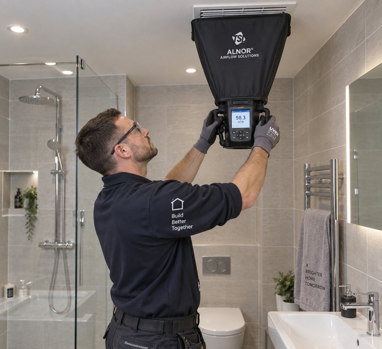
How to prevent it: Specify fans by their installed airflow performance, not their free-air rating. A fan rated at 25 l/s in free air might deliver only 12 l/s at the end of a 3-metre duct run with two bends. Always check the fan's performance curve against the actual system resistance. Then commission the installation: measure airflow at each terminal with a calibrated flow hood, compare the result to the Part F minimum for that room, and record the data on a commissioning sheet. Building Control can — and increasingly does — request these sheets before issuing a completion certificate.
You would be surprised how many window installers — and homeowners arranging their own replacements — have no idea that swapping old windows for new ones triggers Part F obligations. They see it as a straightforward like-for-like swap. The regulations see it differently: replacing a window is work on a controlled fitting, and the replacement must provide ventilation at least as good as what existed before.
Why it matters: If the original window had a trickle vent and the replacement does not, the dwelling's background ventilation has been reduced. In a room with no other ventilation pathway — no wall vent, no mechanical supply — that reduction can push the dwelling below its required whole-dwelling ventilation rate. Part f ventilation mistakes window replacement are among the most common triggers for enforcement action, particularly against installers registered with competent person schemes like FENSA or Certass, who are expected to self-certify compliance.
How to prevent it: Treat every window replacement as a ventilation assessment. Before removing the old unit, check whether it has a trickle vent and note the equivalent area if marked. Specify the replacement window with a vent that meets or exceeds that figure — ideally meeting the current Part F minimum for the room type, not just matching the old provision. If the existing room already has a wall-mounted background ventilator delivering the required equivalent area, document it. Never rely on a homeowner's assurance that they will "add vents later" — a signed disclaimer has no legal standing under the Building Regulations.
This is the mistake that creeps up on buildings over time rather than appearing at a single installation. A homeowner insulates the loft, draught-strips the doors, adds external wall insulation, replaces all the windows, and seals around pipe penetrations — each project sensible on its own. But collectively, these improvements can transform a moderately leaky dwelling into a significantly airtight one, eliminating the incidental infiltration that was silently providing a large share of its ventilation.
Why it matters: As QS Consultants highlight, increasing airtightness without upgrading the ventilation strategy risks condensation, mould growth, and structural moisture damage. A dwelling that previously sat at 10 m³/h/m² at 50 Pa — where System 1 natural ventilation worked adequately — might drop to 5 m³/h/m² or below after a full retrofit programme. At that point, trickle vents alone may no longer draw enough air through natural pressure differences. The existing ventilation strategy becomes insufficient for the new airtightness level, even though no single project was "wrong" in isolation.
How to prevent it: Whenever undertaking energy-efficiency improvements that affect the building envelope, reassess the ventilation strategy as part of the same project scope. If post-retrofit airtightness is expected to fall below 5 m³/h/m² at 50 Pa, consider upgrading from System 1 to System 2 (continuous mechanical extract) or System 4 (MVHR). At minimum, verify that the existing trickle vent provision meets the current Part F equivalent area requirements for every habitable room and wet room. An air permeability test before and after the retrofit work provides hard data to support the ventilation assessment — and gives Building Control confidence that the completed dwelling meets both Part L and Part F simultaneously.
What connects all four mistakes is a single theme: ventilation is treated as an afterthought rather than an integral part of the building work. Fans are picked from a shelf, vents are omitted to save a few pounds, and airtightness improvements proceed without anyone asking what happens to the air supply. The remedy is equally consistent — plan the ventilation alongside the building work, specify to the published rates, and verify the result through commissioning.
That last step — commissioning — is more than a box-ticking exercise. It is a regulatory requirement with its own documentation trail, sign-off process, and handover obligations that directly affect whether Building Control issues a completion certificate.
A ventilation system that is correctly specified on paper but never tested in practice is, in regulatory terms, an unfinished installation. Building Control will not issue a completion certificate until mechanical ventilation systems have been formally commissioned — and the documentation proving it has been submitted. Yet commissioning remains the least understood step in the entire Part F process. Architects rarely detail it in their specifications. Contractors often treat it as somebody else's responsibility. Homeowners have never heard of it. The result? Delayed sign-offs, failed inspections, and completion certificates held hostage over a missing sheet of paper.
Here is exactly what part f ventilation commissioning requirements involve, what documentation you need, and how to avoid becoming one of the projects that stalls at the finish line.
Commissioning is the process of verifying, through physical measurement, that every mechanical ventilation component in a dwelling achieves the airflow rates it was designed to deliver. It is not a visual inspection. It is not a check that the fan switches on. It is a quantified test — measuring the actual litres per second flowing through each extract grille, each supply diffuser, and each terminal in the system — and comparing those measured values against the design specification and the Part F minimums.
Imagine you have installed a System 2 MEV setup in a three-bedroom flat. Commissioning means placing a calibrated flow hood over the bathroom extract grille and reading, say, 9.2 l/s on boost — then checking that against the 8 l/s minimum for a bathroom continuous extract. You repeat this at the kitchen terminal, the utility room, and any other wet room. You verify that the aggregate continuous low-rate extraction across all terminals meets or exceeds the whole-dwelling ventilation rate for a three-bedroom dwelling. And you record every reading.
For System 4 (MVHR), commissioning is more involved. Both supply and extract airflows must be measured at every terminal and balanced so that the system operates at its designed flow ratios. An unbalanced MVHR unit — one that extracts significantly more than it supplies, or vice versa — will either depressurise the dwelling (pulling unconditioned air through gaps in the fabric) or pressurise it (driving moist indoor air into the building structure, risking interstitial condensation). Neither outcome is acceptable.
Commissioning should be carried out by a competent person — someone with the training, equipment, and experience to take accurate airflow measurements and interpret the results. There is no formal accreditation scheme mandated by the regulations, but Building Control bodies increasingly expect commissioning to be performed by individuals with relevant qualifications, such as those certified through manufacturer training programmes or industry bodies like BEAMA.
The timing matters too. Commissioning must happen after the system is fully installed, all ductwork is connected and sealed, all terminals are fitted, and the dwelling is substantially complete — meaning doors are hung, ceilings are finished, and the building envelope is in its final condition. Testing a system in an incomplete shell gives unreliable results because pressure relationships change as the building is sealed up.
Completing the physical tests is only half the task. The other half is the paperwork — and this is where many projects stumble. Approved Document F Volume 1 includes a domestic ventilation commissioning sheet in its Appendix C, and this document (or an equivalent) must be completed for every dwelling with a mechanical ventilation system. As BEAMA's published guidance confirms, the completed commissioning sheet must be submitted to the building control body within five days for new dwellings, or within 30 days in all other cases.
A copy of the completed sheet must also be given to the building owner. This is not optional — it is a regulatory requirement designed to ensure the owner has a record of what was installed, how it was tested, and what the measured performance figures were. Alongside the commissioning sheet, the building owner must receive operating and maintenance instructions for the ventilation system, covering how to use the controls, when to clean or replace filters, and how to identify signs that the system is underperforming.
Here is a complete list of the commissioning and handover documentation that Part F expects:
Building Control may request any or all of these documents before issuing a completion certificate. In practice, the commissioning sheet is the document most frequently requested — and the one most frequently missing. Without it, building control ventilation commissioning sign off stalls, and the project cannot be formally completed. For housebuilders delivering multiple plots, a single missing commissioning sheet can hold up sales completions and trigger contractual penalties.
Commissioning failures are expensive to fix after the fact. Replacing an undersized fan means access panels, re-wiring, and re-testing. Swapping a trickle vent that delivers insufficient equivalent area means removing a window bead, machining a new slot, or even replacing the entire frame. The far cheaper and faster approach is to specify compliant components from the outset — verifying their declared performance data against Part F requirements before they arrive on site, not after Building Control flags a shortfall.
For mechanical ventilation units, this means selecting fans with published performance curves that show the delivered airflow rate at the system resistance your ductwork layout will create — not the free-air figure printed on the box. A fan rated at 30 l/s in free air might deliver only 18 l/s through 4 metres of 100 mm duct with three bends. If the Part F minimum for that kitchen is 30 l/s intermittent, the fan is non-compliant in its installed condition. Check the curve. Match the system.
For background ventilators, the same logic applies. Specifiers and window manufacturers should choose trickle vents with verified equivalent area data tested to the relevant standards, along with documented airflow performance that can be presented to Building Control as evidence of compliance. Products with unclear or untested equivalent area figures create risk — risk that the measured installed performance falls short, that commissioning fails, and that remedial work delays the project.
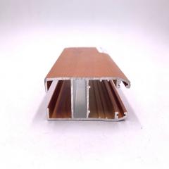
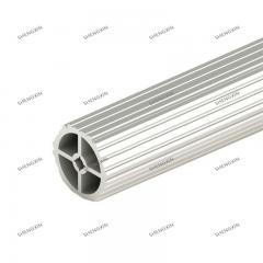
This is where sourcing decisions directly affect compliance outcomes. Shengxin Aluminium's window trickle vents, for example, are designed as frame-ready passive ventilation systems for aluminium and uPVC windows, with documented performance characteristics that allow specifiers to verify equivalent area compliance before the window enters production. For professionals sourcing components that need to satisfy Part F on first inspection, products with this level of documented data streamline the approval process considerably.
Beyond individual component selection, a few broader practices help ensure the whole approval process runs smoothly:
Part F compliance is not a single hurdle cleared at one point in the project. It is a chain — design, specification, installation, commissioning, documentation, handover — where every link must hold. Break one, and the completion certificate stays in the Building Control officer's drawer. But get it right from the start, and what looks like a complex regulatory obligation becomes a straightforward, repeatable process: choose the right system, size the components to the published rates, install them properly, prove they work, and hand the occupant everything they need to keep the system running for years to come.
Approved Document F Volume 1 prescribes specific minimum extract rates in litres per second for each wet room type. A kitchen with a cooker hood adjacent to the hob requires 30 l/s intermittent or 13 l/s continuous boost, while a remote kitchen fan needs 60 l/s intermittent. Bathrooms require 15 l/s intermittent or 8 l/s continuous boost, utility rooms need 30 l/s intermittent or 8 l/s continuous boost, and WCs require 6 l/s for both intermittent and continuous extract. These figures are the compliance benchmarks that Building Control officers verify during commissioning, and falling short on even one terminal can result in a failed inspection.
Yes, in most cases. Replacing windows is classified as work on a controlled fitting under the Building Regulations. If the original window had a trickle vent, the replacement must include one with at least the same equivalent area — ideally meeting the current Part F minimum for that room type. Even if the old window lacked a trickle vent, one may still be required if the room has no other background ventilation provision. A night-latch position on a window is explicitly not an acceptable substitute. Specifiers should choose frame-ready trickle vents with verified equivalent area data, such as those designed for aluminium and uPVC profiles by manufacturers like Shengxin Aluminium, to ensure compliance from the point of manufacture.
Approved Document F defines four system strategies. System 1 uses natural ventilation via trickle vents with intermittent extract fans in wet rooms — the most common setup in traditional housing. System 2 uses continuous mechanical extract (MEV) from wet rooms with passive air supply through trickle vents, suited to moderately airtight dwellings. System 3 provides continuous filtered mechanical supply to habitable rooms with intermittent extract in wet rooms, useful in polluted or urban locations. System 4 is MVHR, delivering balanced mechanical supply and extract with heat recovery, designed for highly airtight new builds below 3 m³/h/m² at 50 Pa. The correct choice depends on dwelling type, airtightness level, energy targets, and budget.
Part L drives tighter building envelopes to reduce energy loss, but airtight construction eliminates the incidental infiltration that older buildings relied on for ventilation. Below approximately 5 m³/h/m² at 50 Pa, passive air supply through trickle vents becomes unreliable, making mechanical ventilation (System 3 or 4) essential. Part O, introduced in 2022, requires overheating mitigation in new residential buildings — often through openable windows that also serve Part F purge ventilation. However, in acoustically sensitive locations near roads or railways, opening windows for cooling may conflict with noise requirements. Designers must coordinate these three regulations early, resolving competing demands on the same window openings through careful specification of ventilation pathways.
Building Control expects a completed domestic ventilation commissioning sheet — included as Appendix C in Approved Document F — recording the system type, terminal locations, design airflow rates, measured airflow rates, and the commissioning engineer's details. This must be submitted within five days for new dwellings or 30 days for other projects. Additionally, the building owner must receive ventilation system operating instructions, a maintenance schedule with filter replacement intervals, a system layout schematic, product data sheets for key components, and confirmation of background ventilator provision with equivalent area figures per room. Missing any of these documents can delay or prevent completion certificate issuance.



 Onlineservice
 0086 136 3563 2360
 sales@sxalu.com
 +86 136 3563 2360
 Deutsch
 English
 français
 русский
 español
 português
 العربية
 ไทย
ไทย Việt
Việt Українська