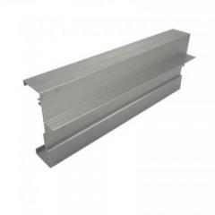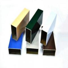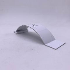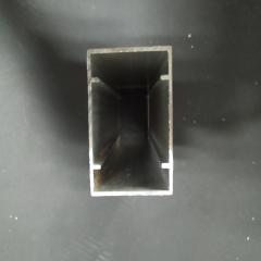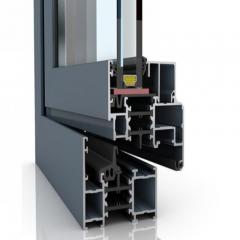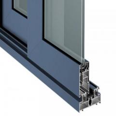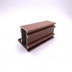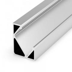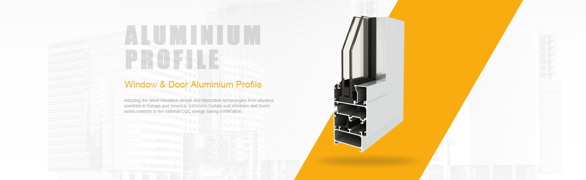
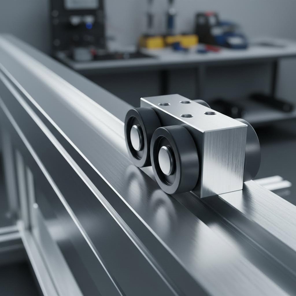
Have you ever wondered how a 3D printer moves its print head with such precision? Or how CNC machines achieve their smooth, repeatable cuts? The answer often lies in a deceptively simple technology: aluminum extrusion linear motion systems. These systems combine lightweight extruded aluminum profiles with specialized bearings to create the backbone of modern precision machinery.
Aluminum extrusion linear motion is a mechanical system where carriages, bearings, or rollers travel along the geometric features of extruded aluminum profiles, enabling controlled, precise movement along a single axis.
Unlike traditional steel rails that require separate mounting structures, these systems integrate the rail directly into the profile itself. This means your frame and your motion system become one unified component, dramatically simplifying design and assembly.
The magic happens in the profile geometry. When you look at an aluminum extrusion rail, you'll notice channels running along its length. These aren't just for attaching accessories. They're engineered pathways that guide motion components with remarkable accuracy.
T-slot profiles feature characteristic T-shaped grooves that accommodate specialized linear bearings. According to 80/20's technical documentation, these bearings are designed to minimize friction while ensuring consistent, predictable movement along the profile. The result? Smooth sliding motion that's self-lubricating and requires minimal maintenance.
V-slot profiles take a different approach. Their beveled edges create angled grooves where V-wheels can roll freely. This design effectively doubles as a linear rail, which significantly reduces parts costs for motion control applications. Imagine rolling a marble along a perfectly straight groove—that's essentially how V-wheel systems glide along extruded aluminium rails.
Why has this technology become so essential? Consider what manufacturers need:
These advantages explain why you'll find 80/20 aluminum and similar extruded aluminum rails powering everything from industrial automation systems to hobbyist CNC routers. According to industry sources, common applications include machine frames, safety enclosures, robotic systems, 3D printers, and ergonomic workstations.
The real game-changer? You don't need specialized training to work with these systems. Anyone can insert a connector into a T-slot extrusion and secure it with basic tools. Need to reconfigure your setup? Simply loosen, adjust, and retighten. This accessibility has democratized precision motion, putting professional-grade linear rail systems within reach of small shops, makers, and engineers worldwide.
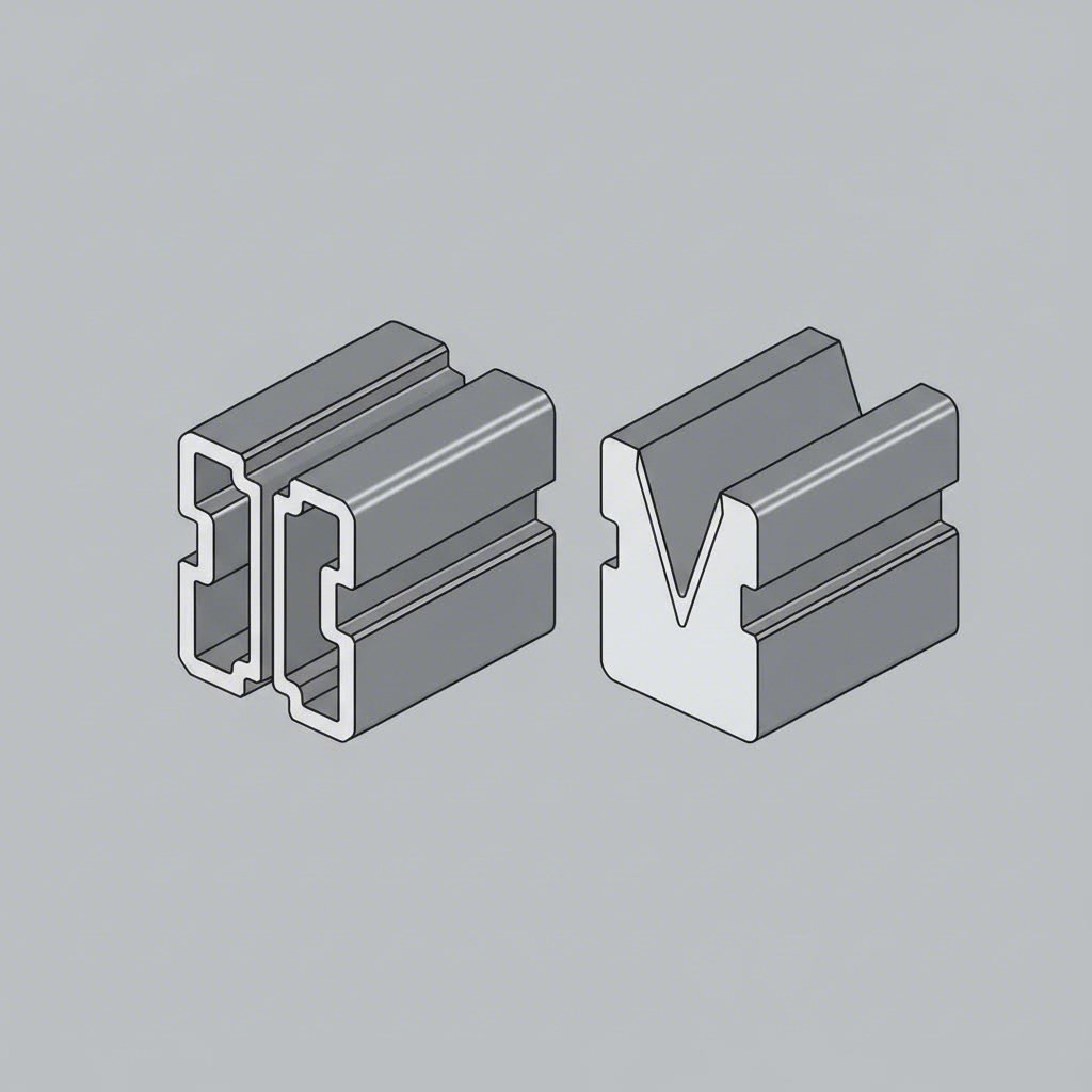
So you understand that aluminum extrusions power modern motion systems—but which profile type should you actually choose? This is where many builders get stuck. The v slot vs t slot debate isn't about which is "better" overall. It's about matching the right geometry to your specific application requirements.
Let's break down exactly how these two profile types differ and when each one shines.
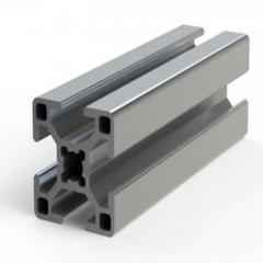
Picture a T-slot profile from the end. You'll see that distinctive T-shaped channel running along each face. This groove design serves a dual purpose: it captures T-nuts for component mounting, and it accommodates linear bearings that slide along the profile surface.
According to technical analysis from industry manufacturers, T-slot profiles excel in applications demanding structural strength and versatility. The open slot design allows hardware insertion at any point along the profile length, giving you maximum flexibility for joint placement and component positioning.
What makes t rail extrusion particularly effective for linear motion?
However, T-slot systems require separate linear motion components when movement is needed. This adds cost and complexity—but also allows you to optimize structural and motion elements independently.
Now examine a v slot extrusion profile. Notice those angled V-shaped grooves along the edges? These aren't just aesthetic. They're precision-ground pathways engineered specifically for V-wheels to roll along.
This is where v slot extruded aluminum truly differentiates itself. As robotics experts explain, the V-groove design allows the structural frame to double as a linear motion guide. You're essentially eliminating separate linear rails by integrating motion capability directly into your framework.
The v slot approach offers compelling advantages for specific applications:
The tradeoff? V-slot profiles require specialized wheels and bearings that may need periodic replacement. They're also optimized primarily for motion applications rather than maximum structural rigidity.
Both T-slot and V-slot profiles come in standardized series sizes that dramatically affect linear motion performance. According to profile manufacturers, common metric dimensions include 20mm, 30mm, 40mm, and 45mm series, while inch-based systems typically use 1" and 1.5" series.
Larger profiles provide greater strength and rigidity but increase weight and cost. For linear motion specifically, profile size affects:
| Characteristic | T-Slot Profiles | V-Slot Profiles |
|---|---|---|
| Groove Geometry | T-shaped channel for T-nuts and bearings | Angled V-shaped grooves for wheel guidance |
| Bearing Compatibility | Linear ball bearings, roller assemblies | V-wheels with precision bearings |
| Load Distribution | Wide contact surfaces for heavy loads | Point contact on angled groove faces |
| Precision Capability | High (with quality linear bearings) | Moderate to high (depends on wheel quality) |
| Ideal Use Cases | Heavy-duty CNC, industrial automation, high-vibration environments | 3D printers, light CNC, pick-and-place, rapid prototyping |
| Hardware Availability | Extensive ecosystem, multiple suppliers | More specialized, fewer sources |
| Assembly Complexity | Multiple fasteners per joint required | Faster assembly with fewer components |
Understanding these distinctions helps you match your selection to real-world requirements. Choose T-slot when you need maximum structural versatility and proven industrial reliability. Opt for V-slot when integrated motion capability and cost-effective compact design are priorities.
But profiles alone don't create motion—you also need the right components to interface with them. Let's examine the bearings, rollers, and wheel systems that bring these extrusions to life.
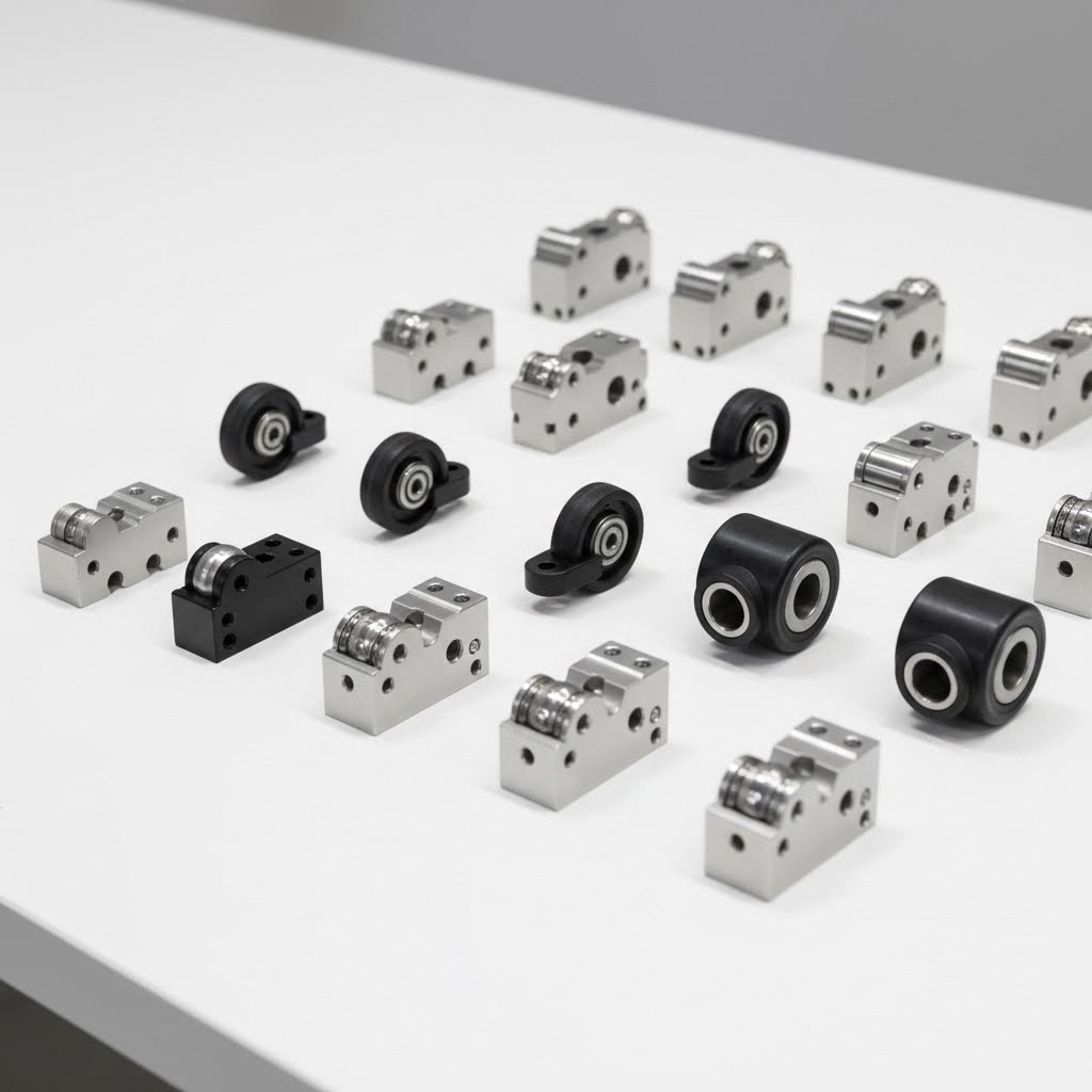
You've selected your profile type—but now comes the critical question: what actually moves along that extrusion? The components you choose determine everything from smoothness and precision to maintenance requirements and lifespan. Think of the profile as the highway and these components as the vehicles traveling on it. Matching them correctly makes all the difference.
Let's explore the four primary component categories that interface with aluminum extrusion systems, along with when to use each one.
When precision matters most, linear bearings are your go-to solution. These components use recirculating ball bearings housed in a carriage that slides along the profile surface. According to 80/20's technical guide, their linear bearings are self-lubricating with rounded edges for smooth operation—critical features for consistent performance.
Here's what you need to know about each component type:
The modularity concept here is powerful. Because T-slot integration allows components to attach anywhere along the profile, you can reposition bearings, add new ones, or completely reconfigure your system without drilling, welding, or permanent modifications. Need to extend your travel length? Simply swap to a longer profile and reinstall your existing components.
Vrails and linear v systems using wheel-based motion have exploded in popularity, especially among 3D printer builders and light CNC enthusiasts. But what makes them work—and when should you choose wheels over bearings?
V-wheels interface with V-slot profiles through angled contact surfaces. As technical comparisons reveal, this approach offers distinct advantages:
However, wheel systems have limitations. The polymer materials wear over time—especially under heavy use or high loads. Standard Delrin wheels may need replacement every few hundred hours in demanding applications. Polycarbonate and metal wheels last longer but cost more and may increase noise levels.
Your bearing or wheel selection is only half the equation. You also need to decide how to actually power that motion. Three primary drive mechanisms work with aluminum extrusion linear motion systems, each optimized for different requirements.
According to actuator selection experts, here's how they compare:
| Criterion | Belt-Driven | Ball-Screw | Linear Bearing (Slide) |
|---|---|---|---|
| Speed Capability | Highest—ideal for rapid positioning | Moderate—limited by screw pitch | Depends on external drive |
| Positioning Accuracy | Moderate—belt stretch affects precision | Highest—sub-micron possible | Moderate to high |
| Load Capacity | Lower—best for light payloads | High—excellent for vertical lifts | Varies by bearing type |
| Maintenance Needs | Low—self-lubricating belts | Moderate—requires lubrication | Low to moderate |
| Noise Level | Quiet operation | Moderate | Very quiet with polymer bearings |
| Best Applications | Pick-and-place, 3D printers, packaging | CNC machining, precision positioning | Drawer glides, adjustable workstations |
Belt-driven systems excel when you need speed and long stroke lengths without extreme precision requirements. Ball-screw drives deliver when accuracy and load capacity trump speed. And simple linear bearing slides—without active drive mechanisms—work beautifully for manual adjustments, drawer systems, and ergonomic workstations.
The beauty of aluminum extrusion systems? You're not locked into one approach. The same T-slot frame that holds your linear bearings today can accommodate a belt-driven actuator tomorrow. This flexibility lets you prototype quickly, learn what works, and optimize without starting from scratch.
Now that you understand what components are available, the next challenge is matching them to your specific application requirements.
You've explored profiles and components—but how do you actually translate that knowledge into the right system for your project? This is where many builders struggle. Specifications like "repeatability ±0.05mm" or "load capacity 500N" sound impressive, but what do they mean for your CNC router, 3D printer, or automation cell?
Let's cut through the jargon and match real-world applications to the specifications that actually matter.
Different applications prioritize different performance characteristics. A 3D printer values speed and smooth motion. A CNC mill demands rigidity and precision. An ergonomic workstation needs effortless adjustment under varying loads. Understanding these priorities helps you avoid both over-engineering (wasting money) and under-engineering (system failure).
According to linear motion specialists, key selection factors include precision grade, load capacity, motion smoothness, material durability, proper alignment, and environmental resistance. But here's what those factors mean for specific applications:
| Application Type | Primary Requirement | Recommended Profile | Bearing System | Critical Specifications |
|---|---|---|---|---|
| CNC Machines | Precision and rigidity | Heavy-duty T-slot (40mm+ series) | 8020 linear bearing or linear rail v slot with steel wheels | Repeatability ≤0.02mm, high static load rating |
| 3D Printers | Speed with acceptable accuracy | V-slot (2040 slot rail or 20mm series) | Delrin or polycarbonate V-wheels | Low friction, quiet operation, moderate repeatability |
| Automation Equipment | Repeatability and cycle life | T-slot with integrated rails | High-cycle 80/20 linear bearing assemblies | Consistent positioning over millions of cycles |
| Workstations | Ergonomic ease of adjustment | Standard T-slot or V-slot | Aluminum extrusion slider or basic roller bearings | Smooth manual movement, adequate static load capacity |
Notice how the requirements shift dramatically? A CNC machine cutting metal needs a 8020 linear slide system that won't flex under cutting forces—even if that means slower maximum travel speeds. Meanwhile, a 3D printer benefits from lightweight V-wheels that zip the print head around at 200mm/s or faster, accepting slightly lower precision in exchange for speed.
Here's where things get technical—but stay with me, because understanding load capacity can save you from catastrophic failures.
As Matara's engineering team explains, there's a critical difference between static and dynamic load capacity:
Why does this matter? A linear rail system designed only for static loads will likely fail catastrophically in application. According to Matara, failures range from "loss of precision through increased friction or binding due to deformation to total structural integrity failure."
To calculate your required dynamic load capacity, consider this formula:
Total Dynamic Load = (Moving Mass × Gravity) + (Moving Mass × Maximum Acceleration)
Imagine your CNC gantry weighs 5kg and accelerates at 2 m/s². Your static load is roughly 49N (5kg × 9.8 m/s²). But your dynamic load during acceleration jumps to 59N—20% higher. Now factor in cutting forces, vibration, and safety margins, and you'll want bearings rated for at least 2-3 times your calculated dynamic load.
Repeatability specifications tell you how consistently the system returns to the same position. But what does "±0.05mm repeatability" actually mean for your project?
Imagine printing a 100mm cube on your 3D printer. With ±0.05mm repeatability, each layer might land anywhere within a 0.1mm window. For decorative prints? Perfectly acceptable. For precision-fit mechanical parts? You might need tighter tolerances.
For CNC applications, CSK Motions recommends selecting high-precision linear guides where accuracy grade matches your machining tolerances. If you're cutting parts to ±0.01mm, your motion system needs repeatability at least that good—preferably better.
Key factors affecting repeatability include:
Manufacturers often list maximum speeds like "3 m/s" for their linear motion components. But hitting that speed requires more than just capable bearings.
Your actual achievable speed depends on:
For most practical applications, focus on the speed your application actually needs rather than chasing maximum ratings. A 3D printer rarely needs more than 500mm/s travel speed. An automation pick-and-place might require 1-2 m/s. Match your component selection to these real requirements, and you'll optimize cost while ensuring reliable performance.
With your specifications defined, the next step is understanding how to actually integrate these components into a working system.
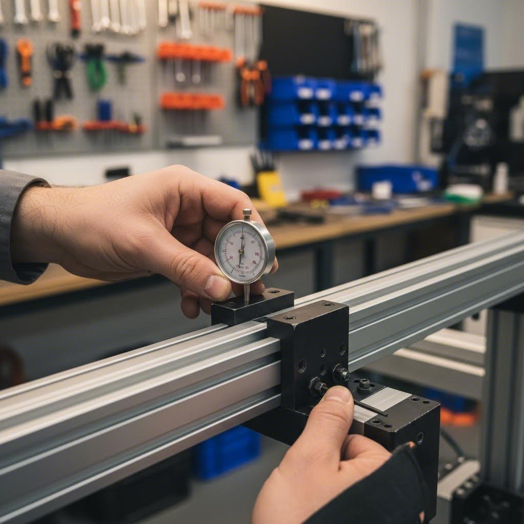
You've selected your profiles, chosen your bearings, and calculated your load requirements. Now comes the moment of truth: actually building the thing. This is where many projects succeed or fail. A perfectly specified system can perform terribly if integration is sloppy—while a modest setup assembled with care often exceeds expectations.
Let's walk through the practical steps of turning components into a functioning motion system.
The connection between your extrusion rail and motion components determines everything from precision to longevity. According to RatRig's installation documentation, proper mounting starts before you even pick up a wrench.
Here's the step-by-step integration process that professionals follow:
The rail button for 8020 aluminum and similar 80 20 accessories simplify this process significantly. These specialized fasteners are designed to drop into T-slots and self-align, reducing the chance of misalignment during assembly.
Here's a truth that surprises many builders: perfect individual components can still create a terrible motion system if they're not properly aligned relative to each other. When mounting parallel rails—which is essential for most gantry designs—the stakes get even higher.
The fixed-and-floating method is your best friend here. As alignment specialists explain, this approach uses one fully secured rail as a reference while allowing the second rail to self-align during assembly:
For 8020 pivot joint configurations and 8020 pivot assemblies, alignment becomes even more critical. These components introduce rotational degrees of freedom that must be properly constrained to prevent unwanted movement during operation.
What about troubleshooting? If you feel sticky spots or binding during motion testing, don't just tighten harder—that makes things worse. Instead, slightly loosen the fasteners in the problem area, cycle the gantry through a few times to allow natural settling, then retighten. According to Vention's documentation, properly aligned profile guide bearings should exhibit resistance force of only 5-8N per bearing. Significantly higher values indicate alignment errors that need correction before putting the system into service.
The investment in proper alignment pays dividends through reduced wear, consistent precision, and dramatically extended component life. Rush this step, and you'll be replacing bearings and troubleshooting performance issues for the life of the machine.
Your aluminum extrusion motion system is assembled and running beautifully. But here's what many builders discover too late: that smooth motion won't last forever without proper care. The good news? A few simple maintenance habits can extend your system's life dramatically—while catching problems before they become expensive failures.
Let's explore how to keep your 8020 linear bearings and v slot rail systems performing at their best.
Think of maintenance like changing your car's oil. Skip it, and you'll pay far more later. According to CSK Motions' maintenance guidelines, regular attention to four key areas prevents most motion system failures.
Cleaning frequency and methods: Dust, metal chips, and debris act like sandpaper on your bearings. For workshop environments, weekly cleaning is recommended. In cleaner settings, monthly may suffice. Use a soft brush for corners and a lint-free cloth with appropriate metal cleaner for rail surfaces. Never use abrasive materials—even fine scratches accumulate over time.
Lubrication schedules: Different bearing types require different approaches:
Fastener inspection: Vibration loosens bolts over time. Check mounting fasteners monthly, retightening any that have backed off. As maintenance experts note, loose fasteners don't just affect performance—they can cause component damage and increase failure risk.
Even with good maintenance, problems develop. Catching them early saves money and prevents catastrophic failures. According to IMTEK Motion's troubleshooting guide, most issues announce themselves through specific symptoms—if you know what to look for.
Here are the warning signs that indicate developing problems:
The diagnostic process: Start with a simple tactile test. Slide the carriage slowly from end to end, feeling for bumps, resistance changes, or sticky spots. Listen carefully—healthy systems run quietly. Then visually inspect all bearing surfaces and rails for damage. Finally, check alignment using a dial indicator if precision is critical to your application.
Most problems you'll encounter are mechanical rather than material failures. According to field experience from motion specialists, cleaning, re-lubricating, and correcting alignment restores most systems to full performance without replacing components. Only when you see deep pitting, flaking, or visible deformation should you consider part replacement.
The bottom line? A few minutes of regular inspection prevents hours of troubleshooting and significant replacement costs. Build maintenance into your routine, and your motion system will reward you with years of reliable service.
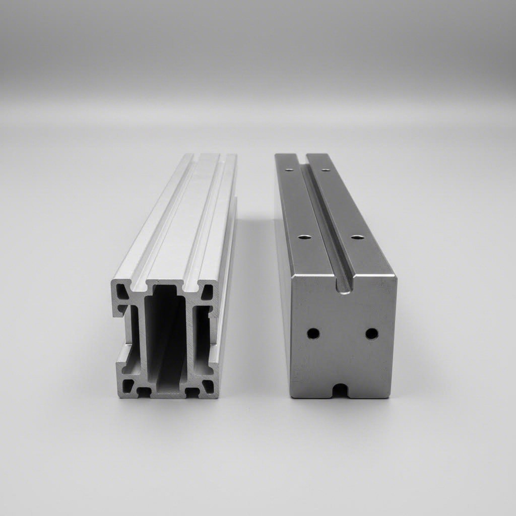
So you're maintaining your aluminum extrusion system beautifully—but was it even the right choice in the first place? This question haunts many builders, especially when they see ultra-precise steel linear rails powering high-end CNC machines. The truth is, neither technology is universally "better." Each excels in specific scenarios, and understanding these distinctions helps you make smarter decisions for current and future projects.
Let's cut through the marketing hype and examine when each motion technology truly shines.
Aluminum extrusion linear rail systems aren't just "budget alternatives" to steel. They offer genuine advantages that make them the superior choice for many applications.
Weight savings that matter: Aluminum weighs roughly one-third of steel. For moving gantries, this difference compounds dramatically. A lighter gantry accelerates faster with the same motor, generates less inertia during direction changes, and puts less stress on the entire frame structure. According to Assembly Magazine's analysis of modular systems, aluminum's strength is comparable to steel while offering flexibility, versatility, and clean visual appearance that steel simply can't match.
Integrated frame construction: Here's where extruded aluminum linear rail systems truly differentiate themselves. Your structural frame and motion system become one unified component. No separate mounting brackets, no precision-ground support surfaces, no complex alignment procedures between rail and structure. The profile IS the rail.
Modularity and reconfiguration: Need to extend your travel length? Add another extrusion section. Want to reposition a bearing? Loosen, slide, retighten. This flexibility proves invaluable during prototyping and development phases. As industry experts note, modifications and changes can be made through all stages of the project—a luxury steel rail installations rarely offer.
Environmental resilience: Guide wheel systems on aluminum profiles routinely operate in environments with low noise requirements, extreme temperatures (from -94°F to 500°F), and washdown practices that would destroy unprotected steel rails. According to Linear Motion Tips, properly configured aluminum guide rails with sealed bearings outperform recirculating ball technology in harsh environments.
Understanding the full cost picture requires looking beyond initial purchase price. Installation time, maintenance requirements, and lifespan all factor into true ownership cost.
| Factor | Aluminum Extrusion Systems | Steel Linear Rails | Stainless Steel Rails |
|---|---|---|---|
| Material Weight | Lightest (~2.7 g/cm³) | Heavy (~7.85 g/cm³) | Heavy (~8.0 g/cm³) |
| Load Capacity | Moderate—suitable for most applications | Highest—industrial heavy-duty | High—with corrosion resistance |
| Precision Grades | ±0.001" (±0.03mm) achievable | Sub-micron possible | Sub-micron possible |
| Initial Cost | Lower—especially for complete systems | Higher—rails plus mounting structure | Highest—premium materials |
| Installation Complexity | Simple—bolt together assembly | Complex—requires precision-ground surfaces | Complex—same as steel |
| Installation Time | Hours for complete systems | Days for precision alignment | Days for precision alignment |
| Corrosion Resistance | Excellent (anodized) | Poor—requires protection | Excellent |
| Best For | Modularity, prototyping, weight-sensitive applications | Ultra-high precision, maximum rigidity | Corrosive environments, food/medical |
The installation time difference deserves special attention. According to Assembly Magazine's case study, a control console using welded steel would take about 2 days to build compared with aluminum structural framing, which can be assembled in only hours. For development projects where iteration speed matters, this difference alone often justifies the aluminum linear rail approach.
Let's be honest: steel linear rails exist for good reasons. When your application demands the absolute highest precision—we're talking sub-micron repeatability for semiconductor manufacturing or aerospace machining—hardened steel rails deliver performance that aluminum simply cannot match.
Steel rails excel when:
Stainless steel adds corrosion resistance for food processing, pharmaceutical manufacturing, and marine environments—but at significant cost premium.
Here's the decision framework that experienced builders use:
Choose aluminium extrusion linear rail systems when:
Choose steel linear rails when:
Many successful machines actually combine both technologies. A steel-rail gantry might mount to an aluminum extrusion frame, leveraging the precision of steel where motion happens while enjoying aluminum's modularity for the structure. This hybrid approach often delivers optimal cost-to-performance ratios.
Understanding these tradeoffs positions you to source components intelligently—which brings us to finding quality extrusions and ensuring they meet your motion application requirements.
You've designed your motion system, selected your bearings, and calculated your load requirements. But here's a reality that trips up many builders: not all aluminum extrusion rails are created equal. The profile you source directly impacts how smoothly your bearings glide, how precisely your gantry positions, and how long your system lasts before requiring replacement.
Let's examine what separates quality aluminium rail extrusions from problematic ones—and how to find suppliers who deliver what your motion application demands.
When aluminum extrusion rails serve as linear guides, dimensional tolerances become critical. According to Standard Machining's tolerance guide, no manufacturing process is perfect—tolerances define the acceptable range of variation that still allows parts to function as intended.
For motion applications, three quality factors demand your attention:
Dimensional tolerances: These control the cross-sectional dimensions of your profile—height, width, and the geometry of those critical V-grooves or T-slots. Standard tolerances from The Aluminum Association serve most general applications, but motion systems often benefit from precision (tight) tolerances. As tolerance experts note, "Precision tolerances are stricter than standard ones. You need them for parts that require a precise fit or have complex assembly requirements."
What does this mean practically? A v slotted aluminum insert riding on an out-of-spec groove will exhibit inconsistent preload—tight in some spots, loose in others. This creates the binding and sticky spots that plague poorly-sourced systems.
Surface finish requirements: The bearing contact surface must be smooth enough for consistent motion but not so polished that lubricants won't adhere. Look for these specifications:
Alloy specifications: The 6063 aluminum alloy dominates motion applications for good reason. According to tolerance specialists, "Softer alloys, like 6063, are easier to extrude and can often hold tighter tolerances." This alloy offers excellent corrosion resistance, good strength-to-weight ratio, and machines cleanly for secondary operations.
For higher-strength requirements, 6061 aluminum provides increased load capacity—though it's slightly more challenging to extrude to tight tolerances. The temper designation (T5, T6, etc.) affects dimensional stability after heat treatment, which matters for precision aluminium extrusion rail applications.
That beautiful anodized finish on your aluminum extruded rail isn't just cosmetic. Surface treatments directly impact bearing compatibility and wear characteristics.
Anodizing considerations: The anodization process creates a hard aluminum oxide layer that improves wear resistance—but it also adds thickness. According to bearing material specialists, aluminum's natural properties include high load capacity and excellent heat conductivity. Anodizing enhances these properties while providing corrosion protection.
However, anodized surfaces require specific attention:
Powder coating, while excellent for structural applications, typically isn't recommended for bearing contact surfaces. The coating thickness is inconsistent and can flake under repeated bearing contact.
Off-the-shelf profiles work for many projects. But when your motion application demands specific dimensions, integrated mounting features, or optimized cross-sections, custom extrusion becomes valuable.
Here's what to evaluate when selecting an extrusion partner for aluminum extrusion rails:
Die development capabilities: Custom profiles require precision dies. Quality suppliers invest in expert die making—as tolerance documentation emphasizes, "A well-designed and precisely manufactured die compensates for potential material flow issues." Ask about die life, revision capabilities, and whether dies remain your property.
Deep processing services: Raw extrusions rarely arrive ready for immediate integration. Look for suppliers offering comprehensive CNC machining capabilities—precise cutting to length, drilling for mounting holes, and bending for complex geometries. These secondary operations, performed in-house, maintain tighter tolerances than farming work to third parties.
Press capacity and flexibility: Different profile sizes require different press tonnages. For example, Shengxin Aluminium's facility operates 35 extrusion presses ranging from 600T to 5500T, enabling production of everything from small 20mm series profiles to heavy-duty 100mm+ industrial sections. This range matters when your project includes both lightweight motion components and structural frame members.
Quality control processes: Request documentation on dimensional inspection procedures. Does the supplier check profiles against tolerance tables? Do they verify straightness and twist—critical for motion rails? Engage early in your design process, as experienced extruders can provide feedback on manufacturability that prevents costly redesigns.
Motion system development typically progresses through stages, and your sourcing strategy should adapt accordingly.
Prototyping phase: Standard profiles from distributors offer quick delivery for concept validation. Accept that tolerances may vary between batches—you're testing function, not final precision.
Development phase: As designs stabilize, work with suppliers offering technical support from design through production. Custom die development makes sense when standard profiles require excessive machining or compromise performance.
Production phase: Factory-direct pricing becomes important at volume. Suppliers with end-to-end capabilities—from extruding raw billets through final surface treatment and precision cutting—deliver consistent quality while eliminating coordination headaches between multiple vendors.
The extruded aluminum railing that works perfectly in your prototype must perform identically across hundreds or thousands of production units. This consistency comes from partnering with manufacturers who control the entire process rather than assembling components from multiple sources.
With quality extrusions in hand, you're ready to plan your complete motion system implementation—from initial specifications through final assembly and beyond.
You've absorbed a lot of information—profiles, bearings, load calculations, alignment techniques, and sourcing strategies. But how do you pull it all together into a successful project? Whether you're building a custom CNC router, automating a production line, or prototyping the next breakthrough 3D printer, a systematic approach separates frustrating builds from machines that perform beautifully from day one.
Let's synthesize everything into an actionable framework you can follow from concept through completion.
Think of this as your roadmap. Each step builds on the previous one, and skipping ahead often creates problems that force you to backtrack. According to Vention's design guidance, successful implementation begins by thoroughly analyzing your design, load characteristics, and workflow needs before selecting any components.
With your plan established, execution becomes straightforward. Here's how to move from planning to a functioning machine:
Start with structure, then add motion: Build and verify your frame's squareness before installing any linear components. A twisted frame dooms even the best bearings to poor performance. Use quality levels and squares during assembly—the few extra minutes invested here save hours of troubleshooting later.
Test incrementally: Don't wait until everything is assembled to discover problems. After mounting each v rail or bearing assembly, slide the carriage through its full travel. Feel for binding, listen for unusual sounds, and verify consistent resistance throughout the stroke. Fix issues immediately rather than hoping they'll resolve themselves.
Document your setup: Record bearing preload settings, fastener torque values, and lubrication intervals. This information proves invaluable when maintaining the system or building identical machines later.
Plan for evolution: One of aluminum extrusion's greatest strengths is reconfigurability. Design your system anticipating future modifications. Leave T-slots accessible for additional components. Use standard fastener sizes across your build. This foresight transforms a static machine into a platform that grows with your needs.
Complex motion projects benefit enormously from working with experienced suppliers who understand both extrusion manufacturing and linear motion requirements. Technical support during the design phase catches potential problems before they become expensive mistakes. Factory-direct pricing at production volumes improves project economics. And comprehensive capabilities—from custom die development through precision CNC machining and quality surface treatments—ensure your profiles arrive ready for immediate assembly.
Suppliers like Shengxin Aluminium, with over 30 years of experience and 35 extrusion presses ranging from 600T to 5500T, exemplify this end-to-end approach. Their technical team supports projects from initial concept through mass production, which proves particularly valuable for specialized linear motion applications requiring custom profile geometries or tight dimensional tolerances.
Whether you're building your first motion system or your hundredth, the principles remain consistent: understand your requirements thoroughly, match components to those requirements carefully, assemble with attention to alignment, and maintain your system proactively. Follow this framework, and your aluminum extrusion linear motion system will deliver the precise, reliable performance that makes modern automation possible.
T-slot profiles feature T-shaped channels designed for T-nuts and linear bearings, offering superior load-bearing capacity and extensive hardware compatibility for heavy-duty applications. V-slot profiles have angled V-shaped grooves that allow V-wheels to roll directly along the extrusion, integrating the structural frame with the motion guide. Choose T-slot for maximum versatility and industrial reliability, and V-slot when you need integrated motion capability with reduced component count and cost efficiency.
Adding linear motion to 80/20 T-slot systems involves selecting compatible bearings such as linear ball bearings, T-slot roller bearings, or V-wheel assemblies. Mount the bearings directly to the profile surface, ensuring proper alignment using the fixed-and-floating method for parallel rails. Pair with drive systems like belt-driven actuators for speed or ball-screws for precision. Quality suppliers like Shengxin Aluminium offer CNC-machined profiles ready for immediate bearing integration.
The best bearing depends on your application. Linear ball bearing carriages deliver high precision with minimal friction—ideal for CNC machines requiring tight tolerances. T-slot roller bearings handle heavier loads and tolerate contamination better. V-wheel assemblies offer quiet, cost-effective motion for 3D printers and light automation. For high-cycle industrial use, select high-cycle rated bearings with threaded inserts designed for applications with frequent acceleration and deceleration.
Aluminum extrusion systems can replace steel rails in many applications, offering integrated frame construction, weight savings of approximately two-thirds, and faster assembly times measured in hours versus days. They excel for prototyping, weight-sensitive gantries, and applications requiring ±0.03mm precision. However, steel rails remain superior for sub-micron positioning, extreme loads, and long-term dimensional stability in precision machining. Many successful designs combine both—steel rails for motion precision on aluminum extrusion frames.
Regular maintenance extends system life significantly. Clean bearing surfaces weekly in dusty workshops using soft brushes and lint-free cloths. Lubricate linear bearings with manufacturer-recommended grease after cleaning, while V-wheels need light machine oil on their internal bearings every 100-200 hours. Inspect fasteners monthly for vibration loosening. Watch for warning signs including grinding sounds, uneven wear patterns, increased resistance, or dark discoloration in lubricants—addressing these early prevents costly failures.



 Onlineservice
 0086 136 3563 2360
 sales@sxalu.com
 +86 136 3563 2360
 Deutsch
 English
 français
 русский
 español
 português
 العربية
 ไทย
 Việt
 Українська