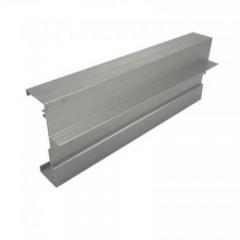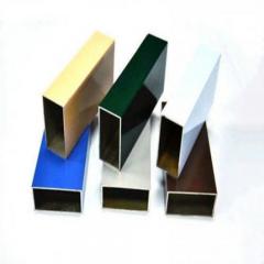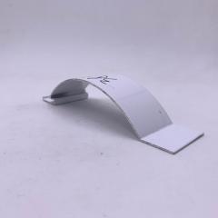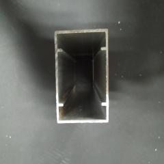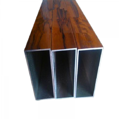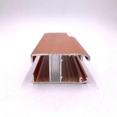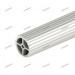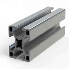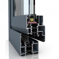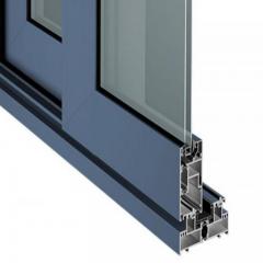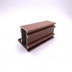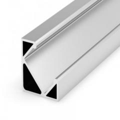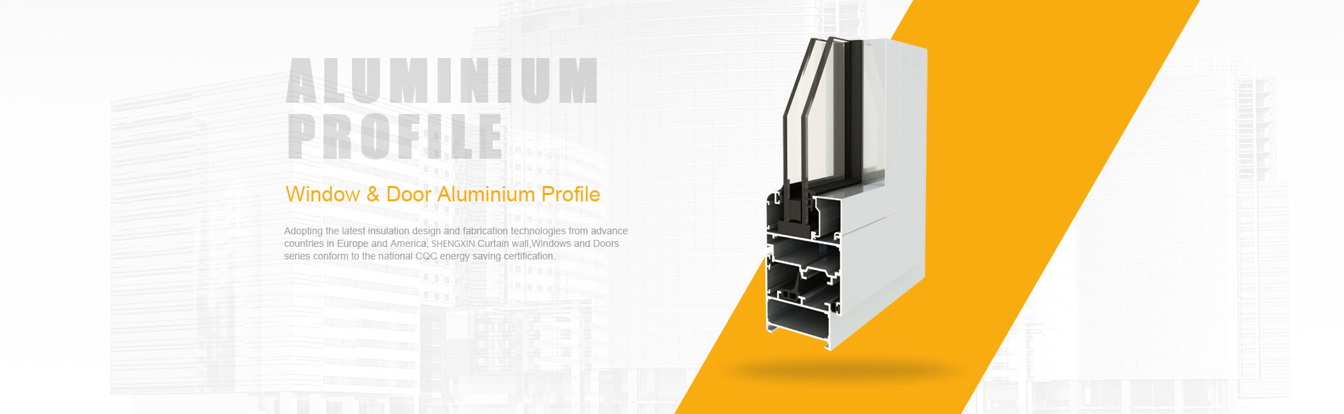
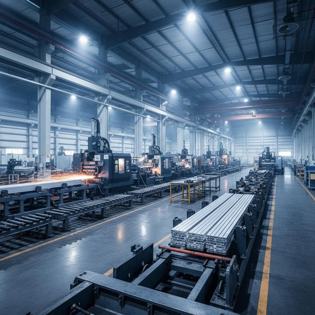
You've seen the sleek aluminum frames on modern buildings, the precise channels inside electronic enclosures, and the structural components holding together everything from solar panels to aircraft interiors. But have you ever wondered what happens between creating a raw aluminum profile and installing that finished component? That's where aluminum extrusion fabrication comes into play.
Aluminum extrusion fabrication refers to all secondary operations performed on extruded aluminum profiles—including cutting, machining, bending, welding, and finishing—that transform raw extrusions into functional, ready-to-install components.
When aluminum billets pass through a die to create profiles, you're only witnessing the first step. The extrusion process produces what manufacturers call "mill-length" sections—typically ranging from 12 to 24 feet long. These raw profiles, whether hollow, semi-hollow, or solid shapes, require extensive processing before they become usable parts. Think of it this way: extrusion creates the raw material, while fabrication transforms that material into something functional.
What exactly does extrusion fabrication involve? The process encompasses five core operations:
Each operation requires specialized equipment and expertise. For instance, aluminum extrusion with iron-based tooling demands careful temperature control to prevent contamination and ensure clean cuts.
Why should engineers, designers, and procurement professionals care about fabrication and assembly details? Because understanding these secondary operations directly impacts project success. The complexity of your extruded profile—whether it's a simple solid shape or an intricate hollow section—determines which fabrication methods are viable and cost-effective. Aluminum extrusion with iron particles in the cutting environment, for example, can compromise anodizing quality if proper separation protocols aren't .
Throughout this guide, you'll discover how to select the right alloys for your fabrication requirements, specify appropriate tolerances, and design profiles that minimize downstream processing costs. This knowledge bridges the gap between knowing what an aluminum extrusion is and understanding how it becomes your finished product.
Ever wondered why some aluminum profiles machine beautifully while others crack during bending? The answer lies in what happens before fabrication even begins. Understanding the aluminum extrusion process isn't just academic knowledge—it's essential for predicting how your profiles will behave during every downstream operation.
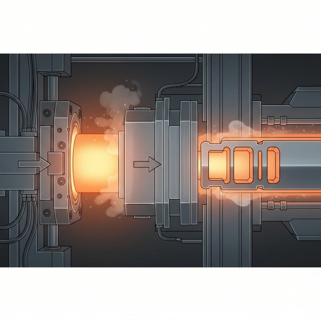
The aluminium extrusion process transforms solid aluminum billets into precisely shaped profiles through a fascinating combination of heat and pressure. Imagine squeezing toothpaste through a shaped nozzle—the principle is similar, though the engineering is far more sophisticated.
Here's how aluminum extrusion works, broken down into the key stages that affect your fabrication options:
Each stage influences what you can—and can't—do during fabrication. A profile that cooled unevenly, for instance, may develop internal stresses that cause distortion when you machine away material.
The shape created during extrusion directly determines your fabrication possibilities. Profile geometry falls into three classifications, each presenting unique challenges:
Wall thickness plays an equally critical role. According to industry design guidelines, minimum practical wall thicknesses range from 0.040 inches for small solid profiles to 0.188 inches or more for larger hollow sections. Why does this matter for fabrication? Thin walls limit your machining depth before breakthrough, restrict welding heat input before burn-through, and reduce bending radii before cracking occurs.
The relationship between extrusion complexity and fabrication requirements follows a predictable pattern. Adjacent wall thickness ratios greater than 2:1 create uneven cooling conditions during extrusion, potentially causing dimensional variations that complicate precision machining. Large circumscribing circles—the smallest circle that encloses the entire profile cross-section—require more powerful presses and typically result in looser tolerances on the as-extruded profile.
What does this mean practically? A complex hollow profile with varying wall thicknesses will require more aggressive straightening, tighter process controls, and potentially additional machining stock to achieve your final dimensions. Conversely, a well-designed profile with uniform walls and rounded internal corners flows through the die more consistently, arriving at your fabrication shop with predictable properties.
Understanding these relationships empowers you to make smarter decisions early in your design process. The next critical decision? Selecting the right aluminum alloy for your specific fabrication methods.
You've designed your profile geometry and understand the extrusion process. Now comes a decision that will affect every fabrication operation downstream: which aluminum alloy should you specify? This choice influences everything from how cleanly your profiles cut to how beautifully they anodize. Get it right, and fabrication flows smoothly. Get it wrong, and you'll battle machining difficulties, welding complications, or disappointing surface finishes.
Not all aluminum extrusion material performs equally during fabrication. The 6000 series alloys dominate the extrusion industry because they contain magnesium and silicon—elements that provide excellent extrudability, good strength, and outstanding corrosion resistance. According to industry specifications, these alloys are heat treatable and offer good machinability, formability, and weldability, making them ideal for manufacturing applications.
But here's where it gets interesting: even within the 6000 series, significant differences exist. Your fabrication requirements should drive your alloy selection, not the other way around. Consider these key factors:
When professionals discuss aluminium alloy extrusion options, two alloys dominate the conversation: 6063 and 6061. Understanding their differences helps you make informed fabrication decisions.
Aluminum 6063, often called the "architectural alloy," excels in applications where appearance matters. According to Metal Supermarkets, this alloy provides superior corrosion resistance, excellent surface quality, and is easily anodized to create attractive colored finishes. Its superior extrudability means manufacturers can produce intricate profile geometries with fine details that maintain crisp edges.
Aluminum 6061, by contrast, prioritizes strength over aesthetics. It contains up to twice the iron content and typically more copper, chromium, and silicon than 6063. These additions boost mechanical performance but reduce finishing response. With a Brinell hardness of 95 compared to 6063's 73, this alloy handles structural demands that would overwhelm its architectural counterpart.
What is extrusion aluminum best suited for in your project? That depends on whether you need strength or beauty—and sometimes both require creative solutions.
Understanding how these alloys behave during specific fabrication operations helps you avoid costly surprises. Here's a comprehensive comparison:
| Property | Aluminum 6063 | Aluminum 6061 |
|---|---|---|
| Machinability | Good – softer material may gum up tooling | Excellent – chips cleanly, holds tight tolerances |
| Weldability | Good – minimal heat-affected zone issues | Good – may require post-weld heat treatment |
| Bendability | Excellent – forms tight radii without cracking | Good – requires larger bend radii |
| Anodizing Response | Excellent – produces uniform, attractive finishes | Fair – may show inconsistent coloration |
| Extrudability | Superior – handles complex die geometries | Good – limited on intricate profiles |
| Brinell Hardness | 73 | 95 |
| Corrosion Resistance | Excellent – ideal for weather exposure | Good – slightly less resistant than 6063 |
| Typical Applications | Window frames, door frames, architectural trim, furniture, lighting fixtures, electrical conduit | Structural frames, aerospace components, truck beds, marine equipment, heat sinks, manifolds |
Notice the trade-offs? Extrusion aluminum in the 6063 grade bends more easily and anodizes beautifully, but 6061 machines more precisely and handles structural loads better. As Protolabs notes, welding 6061 can weaken the heat-affected zone, so post-weld treatment may be necessary—a factor that adds time and cost to your fabrication process.
For round tubing applications, an interesting exception occurs: 6063 actually provides higher product strength due to its superior extrudability in this specific geometry. Square tubing similarly favors 6063 because it delivers better surface finish and corrosion resistance.
The bottom line? Match your alloy selection to your most critical fabrication requirement. Prioritize 6061 when strength and machinability matter most. Choose 6063 when surface appearance, bendability, and corrosion resistance drive your design. With your alloy selected, the next step involves understanding exactly what tolerances each fabrication method can achieve.
You've selected your alloy and understand how the extrusion process affects downstream operations. Now comes the practical question every engineer and designer faces: which fabrication methods should you specify for your project? The answer depends on your tolerance requirements, production volumes, profile geometry, and budget constraints. Let's examine each core method so you can make informed decisions.
Every fabrication project begins with cutting mill-length extrusions to size. But choosing between saw cutting, waterjet, and laser isn't always straightforward. Each method excels in different scenarios.
Saw cutting remains the workhorse of extrusion machining operations. According to industry guides, circular saws with carbide-tipped aluminum blades running at 2,000-3,500 RPM deliver reliable results for most applications. Dimensional accuracy typically falls within ±0.015 inches—perfectly acceptable for general fabrication.
Waterjet cutting uses ultra-high-pressure water (300-400 MPa) mixed with abrasive particles to slice through aluminum without generating heat. This cold-cutting process eliminates thermal distortion—critical for machined aluminum extrusion components requiring tight tolerances.
Laser cutting delivers the fastest cutting speeds—up to 10-20 times faster than manual methods. Fiber lasers operating at 1064nm wavelength paired with nitrogen assist gas prevent oxidation while achieving exceptional edge quality.
When should you choose waterjet over saw cutting? If your design includes curves, internal cutouts, or you're working with thick material that would generate excessive heat with conventional methods, waterjet makes sense despite higher costs. For simple straight cuts in production quantities, saw cutting delivers the best value.
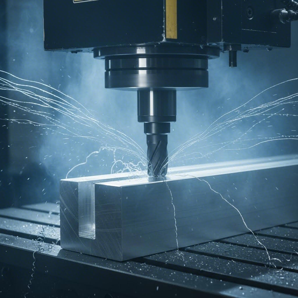
What happens when your extrusion needs holes, slots, threads, pockets, or precision surfaces? That's where CNC machining transforms raw profiles into finished components. As Star Extruded Shapes explains, CNC machining uses computer numerical control to automate cutting operations, enabling repeatability and precision impossible with manual methods.
The metal extrusion process creates your profile shape, but CNC machining adds the features that make it functional. Understanding the three primary operations helps you specify requirements correctly:
Milling removes material using rotating multi-point cutting tools. This operation creates flat surfaces, pockets, slots, and complex 3D contours. Aluminum's excellent machinability—it chips cleanly and doesn't excessively wear tooling—makes it ideal for milling operations.
Drilling creates round holes for fasteners, pins, or access points. While simple in concept, drilling extruded profiles requires proper fixturing to prevent vibration, especially with hollow sections.
Tapping cuts internal threads into drilled holes, allowing bolted connections without additional hardware. Aluminum's softness demands careful speed and feed selection to prevent thread stripping.
When does CNC machining make sense versus manual fabrication? Consider this guideline: if you need more than 20-50 identical pieces or require tolerances tighter than ±0.010 inches, CNC typically delivers better economics and quality. For prototype quantities or simple operations like drilling a few holes, manual methods often prove more practical.
Aluminum extrusion shapes don't always need to remain straight. Bending transforms linear profiles into curves, angles, and complex forms—but only if you understand the material's limitations.
Your alloy selection matters tremendously here. Remember from the previous chapter that 6063 bends more readily than 6061. But profile geometry plays an equally critical role. Hollow sections risk collapse during bending unless properly supported with internal mandrels. Asymmetric profiles complicate matters further, as uneven material distribution causes inconsistent springback.
Press brake bending works well for creating angles in solid or simple profiles. The process positions the extrusion over a die and applies force to create the desired bend angle.
Roll bending produces large-radius curves by passing profiles through a series of rollers. This method handles longer sections and creates sweeping curves for architectural applications.
Stretch forming clamps the extrusion ends and wraps the material around a form die while applying tension. This technique minimizes springback and produces consistent results for complex curves.
When your design requires multiple profiles assembled into a single structure, welding and mechanical joining enter the picture. Aluminum's thermal properties create unique welding challenges—high thermal conductivity rapidly dissipates heat, requiring higher amperage than steel welding.
The extrusion extrusion of oxide layers on aluminum surfaces demands proper cleaning before welding. Unlike steel, aluminum's tenacious oxide layer melts at a much higher temperature than the base metal, preventing proper fusion if not removed. TIG (GTAW) and MIG (GMAW) welding processes work well with proper preparation and technique.
Punching and stamping create holes, slots, and formed features by forcing a hardened tool through the material. These operations work best with thinner wall sections and can achieve high production rates for repetitive features.
Understanding which extrusion extrusion fabrication methods apply to your project helps you communicate effectively with fabricators and optimize your design for manufacturing. But what tolerances can you actually achieve with each method? That's the next critical question to answer.
You've selected your fabrication methods. Now comes the question that separates successful projects from costly rework: what tolerances can you actually achieve? Specifying tolerances too tight wastes money and extends lead times. Specifying them too loose risks parts that won't fit or function properly. Understanding achievable tolerances for each aluminum extrusion processing method empowers you to make smart decisions from the start.
Here's a manufacturing reality many engineers overlook: that ±0.001 inch tolerance you just specified might have doubled your part cost and tripled your lead time. According to Modus Advanced, the relationship between tolerance and manufacturing complexity isn't linear—it's exponential.
Different aluminum extrusion manufacturing processes deliver vastly different precision levels. Understanding these capabilities prevents over-specification on non-critical features while ensuring adequate control where it matters:
| Fabrication Process | Standard Tolerance | Precision Tolerance | Cost Impact |
|---|---|---|---|
| Saw Cutting | ±0.015 to ±0.030 inch | ±0.010 inch | Low baseline cost |
| Waterjet Cutting | ±0.005 inch | ±0.002 inch | Moderate; slower speeds |
| Laser Cutting | ±0.005 inch | ±0.002 inch | Higher equipment costs |
| CNC Milling | ±0.005 inch | ±0.001 inch | 2-4x cost increase for tight tolerances |
| CNC Drilling | ±0.005 inch position | ±0.001 inch position | Moderate increase |
| Tapping/Threading | Class 2B fit | Class 3B fit | Minimal difference |
| Bending | ±1° to ±2° angle | ±0.5° angle | Significant increase; multiple iterations |
| Welded Assemblies | ±0.030 inch | ±0.010 inch | Requires fixturing and post-machining |
According to HLH Rapid, default CNC tolerances are typically controlled to ISO 2768-1 medium, generally around ±0.005 inch (0.13mm) for milled and turned parts. High-precision work can achieve ±0.001 inch (0.025mm), while ultra-precision tolerances ranging from ±0.0002 inch to ±0.0005 inch require specialized equipment and controlled environments.
How do you communicate tolerance requirements effectively to fabricators? The answer lies in understanding tolerance systems and applying them strategically. When you extrude aluminum profiles and send them for fabrication, your drawings must clearly convey intent.
Several tolerance specification systems exist, each suited to different applications:
Standard extrusion tolerances from the Aluminum Association provide baseline dimensional expectations for as-extruded profiles. Cross-sectional dimensions typically allow ±0.006 to ±0.024 inch depending on profile size and whether dimensions involve metal or space. Your fabrication tolerances stack on top of these baseline variations.
Best practices for tolerance specification include:
Understanding when tight tolerances genuinely matter—and when they represent engineering overkill—can transform your approach to design for manufacturability. As metal extruder operations become more sophisticated, the temptation to over-specify grows. Resist it.
Tight tolerances are justified when:
Tight tolerances add unnecessary cost when:
The cost impact of precision escalates dramatically. According to industry data, moving from standard machining tolerances (±0.030 inch) to precision tolerances (±0.001 inch) increases costs by approximately 4x. Ultra-precision tolerances (±0.0001 inch) can cost 24 times more than standard machining. Lead times extend as well—precision work requires temperature-controlled environments, thermal stabilization of machine tools, and specialized inspection routines.
Consider performing a tolerance stack-up analysis for critical assemblies. When multiple parts mate together, their individual tolerances combine to create a final measurement. A worst-case scenario calculation helps prevent fit issues that might otherwise require costly rework or redesign.
With tolerances properly specified, your next consideration becomes equally important: designing profiles that fabricate efficiently from the start.
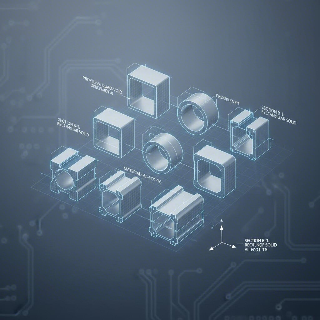
Imagine spending thousands of dollars developing a custom aluminum extrusion die, only to discover that your profile design makes downstream fabrication prohibitively expensive. It happens more often than you'd think. The decisions you make during profile design directly determine how efficiently—and affordably—your extrusions can be cut, machined, bent, and assembled. Understanding design-for-fabrication principles before committing to tooling saves money, reduces lead times, and prevents frustrating rework.
Your aluminum extrusion die creates the foundation for every fabrication operation that follows. According to the Aluminum Extruders Council, profiles are most economical when they fit within a circumscribing circle diameter (CCD) of one to ten inches, with CCDs under eight inches significantly reducing costs. But extrudability is only half the equation—you need profiles that also fabricate well.
What makes a profile fabrication-friendly? Consider these core principles:
Think of your aluminium extrusion line as the first step in a multi-stage manufacturing process. Every design choice you make ripples forward into fabrication costs and capabilities.
Some design decisions seem insignificant during profile development but create major headaches during fabrication. Understanding these common pitfalls helps you avoid expensive corrections:
Deep, narrow channels restrict tool access. That elegant deep pocket in your profile design? It might be impossible to machine because standard end mills can't reach the bottom without excessive deflection. Before finalizing your design, verify that standard tooling can access all features requiring machining.
Hollow sections demand special fixturing. When you clamp a hollow profile for machining, the walls can deflect inward, causing dimensional inaccuracies and chatter marks. Internal mandrels or specialized fixtures add cost and setup time. According to design guidelines, you should limit design details in hollow parts since there's no way to hold internal features in place during forming.
Thin walls limit machining depth. Planning to machine a pocket into a thin-walled section? You'll risk breakthrough before reaching your target depth. As a general rule, maintain at least 0.040 inches of remaining wall thickness after machining to preserve structural integrity.
Asymmetric profiles complicate bending. When material distribution varies across your profile's cross-section, bending creates uneven stress distribution. The result? Unpredictable springback, twisting, and potential cracking. If bending is required, design for symmetry or expect additional trial-and-error during setup.
Sharp corners weaken die tongues. Those crisp 90-degree internal corners look great on drawings but create stress concentrations in the aluminum extrusion dies. Rounded corners strengthen the die, improve metal flow, and often enhance your final product's fatigue resistance too.
Smart designers think beyond extrusion to consider how profiles will be processed along the entire aluminum extrusion line. Here's a decision-making framework for optimizing your design:
For profiles requiring extensive machining:
For profiles requiring bending:
For profiles requiring welding:
For profiles requiring assembly:
The goal isn't just creating a profile that extrudes well—it's creating a profile that flows efficiently through every manufacturing step. When you invest time in design-for-fabrication thinking upfront, you'll see the payoff in faster production, lower costs, and fewer quality issues. With your profile optimized for fabrication, the next consideration becomes equally important: how your fabrication choices affect surface finishing outcomes.
You've cut, machined, bent, and welded your aluminum extrusions to perfection. Now comes a critical question many fabricators overlook until it's too late: how will those fabrication operations affect your final surface finish? That beautiful anodized color you specified might look completely different on machined surfaces versus as-extruded areas. Those welded joints could turn into unsightly dark streaks after finishing. Understanding the relationship between fabrication choices and finishing outcomes prevents disappointing results and costly rework.
Every fabrication operation leaves its mark—literally. Saw cuts create microscopic burrs. CNC machining produces distinct tool patterns. Welding alters the metallurgical structure of surrounding material. These marks and changes directly influence how extruded metal products accept surface treatments.
According to SAF Anodizing & Finishing, anodizing is only as good as the metal you use—it will not hide scratches or water stains. This principle extends to all surface finishes: what you see before finishing, you'll see after finishing, often more prominently.
Before any finishing operation, your metal extrusions require proper preparation:
Anodizing creates a protective oxide layer that grows into the aluminum surface itself. According to Protolabs, this electrochemical oxidation builds protection into the surface at thicknesses of just 5-25 micrometers. Because the process penetrates the metal rather than coating over it, any metallurgical variations become visible.
Here's where welded metal extrusion products present special challenges. According to CY Manufacturing, anodizing color variation on welded parts occurs for five distinct reasons:
The solution? According to industry experts, choosing the right filler alloy is critical. For 6063 extrusions requiring good anodizing color match after welding, use 5356 filler alloy. Never use 4043 filler—it turns a smutty black during anodizing, creating an obvious defect.
Machined surfaces present different challenges. The cutting action exposes fresh aluminum with different grain orientation than the original extruded surface. These areas often absorb anodizing dye more readily, appearing darker than surrounding material. Consistent machining parameters and post-machining surface treatment help minimize this effect.
Different finishing methods have different sensitivities to fabrication-induced surface variations. Understanding these relationships helps you plan your fabrication sequence strategically.
Anodizing Surface Preparation Requirements:
Powder Coating Surface Preparation Requirements:
PVDF and High-Performance Coating Requirements:
According to finishing comparisons, anodizing tolerates higher heat and maintains precise fits because it adds minimal material. Powder coating offers better chip and UV resistance but starts breaking down above 200°C. Your application environment should guide finish selection as much as aesthetics.
One final consideration: repairability. Anodizing is hard to repair without re-anodizing the entire part, while powder coating can be touched up—though color matching isn't always perfect. For extrusion metal components that may see field damage, powder coating often proves more practical despite its other limitations.
With surface finishing requirements understood, the next critical step involves establishing quality control measures that catch defects before they become costly problems.
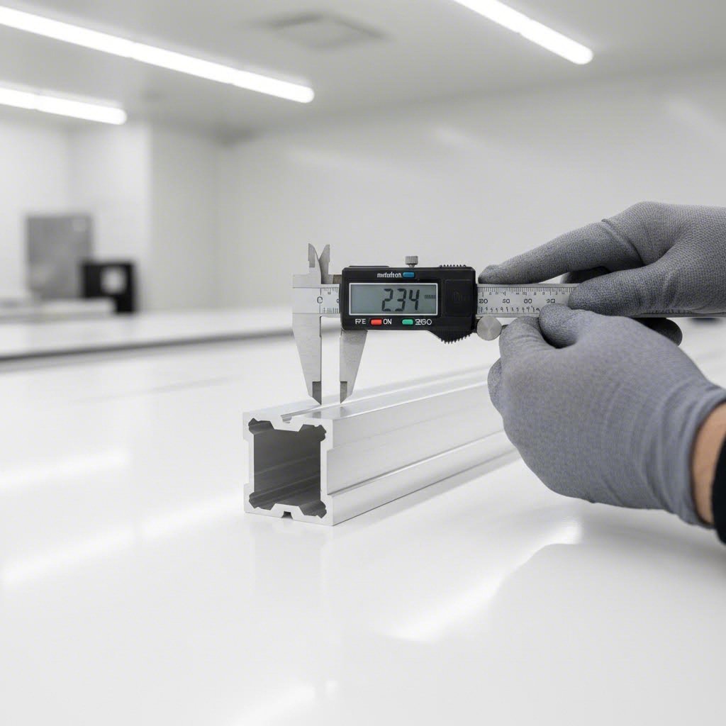
You've designed your profile, selected the right alloy, and specified your fabrication methods. But how do you know the finished components will actually meet your requirements? Quality control in aluminum extrusion fabrication isn't just about catching problems—it's about preventing them before they happen. Understanding inspection methods and common defects empowers you to specify meaningful quality requirements and recognize when something isn't right.
Rigorous quality checks conducted throughout the fabrication process ensure that final products meet specifications and standards. According to industry guidelines, testing and inspection verify part performance, dimensions, and overall quality at multiple stages.
What inspection methods should you expect from a competent fabrication assembly operation? Here are the core techniques:
Dimensional verification confirms that fabricated features match drawing specifications. This includes:
Surface quality assessment identifies visual defects that could affect performance or appearance:
Weld integrity testing ensures joined assemblies will perform under load. According to welding experts, adhering to stringent quality standards like ISO 3834 ensures that every step of the welding process is meticulously controlled:
Understanding what can go wrong—and why—helps you prevent defects rather than just detecting them. When extruding aluminum and performing secondary operations, several common issues arise:
| Defect Type | Common Causes | Prevention Strategies |
|---|---|---|
| Burrs from cutting | Dull saw blades, incorrect feed rates, improper blade tooth geometry | Maintain sharp tooling, optimize cutting parameters, use appropriate blade pitch for wall thickness, implement deburring as standard operation |
| Distortion from welding | Excessive heat input, improper clamping, asymmetric weld sequences | Use balanced welding sequences, preheat when appropriate, employ proper fixturing, control heat input through parameter optimization |
| Cracking from bending | Bend radius too tight, wrong temper condition, material oriented incorrectly | Specify minimum bend radii based on alloy and temper, consider T4 temper for severe bends, orient grain direction appropriately |
| Machining chatter marks | Inadequate workholding, tool deflection, excessive cutting speeds | Improve fixturing rigidity, use shorter tool overhangs, optimize speeds and feeds for aluminum alloys |
| Thread stripping | Incorrect tap size, excessive tapping speed, insufficient lubrication | Verify hole diameter before tapping, reduce speed for aluminum, use appropriate cutting fluid |
| Weld porosity | Contaminated base metal, moisture in shielding gas, improper cleaning | Clean surfaces thoroughly before welding, verify gas purity, remove oxide layer immediately before welding |
| Surface scratches | Improper handling, contaminated work surfaces, inadequate protection | Use protective film during fabrication, train handlers on soft metal care, maintain clean work surfaces |
| Dimensional drift | Tool wear, thermal expansion, fixture loosening | Implement statistical process control, verify first-piece dimensions, monitor tool condition, allow thermal stabilization |
Notice how many defects trace back to preventable causes? According to welding research, aluminum's high thermal conductivity means it heats up and cools down faster than many other metals, leading to significant distortion if not controlled properly. Preheating helps moderate temperature changes and reduces crack formation risk—especially critical when extruding metal components from high-strength 7xxx series alloys.
Effective quality control isn't a single inspection at the end—it's a series of checkpoints integrated throughout your fabrication assembly process. Here's a framework for implementing quality gates:
Incoming material inspection:
First-article inspection:
In-process monitoring:
Final inspection:
According to fabrication best practices, finishing touches should ensure that parts are free from any defects, burrs, or sharp edges before shipping or installation. This final quality gate catches issues that might have developed during handling or secondary operations.
For critical applications, consider implementing statistical process control (SPC) to monitor dimensional trends over time. SPC charts reveal when processes are drifting toward out-of-tolerance conditions, allowing correction before defects occur. This proactive approach costs far less than sorting or scrapping defective parts after the fact.
With quality control systems in place, one major decision remains: should you handle fabrication in-house or partner with a specialized fabricator? The answer depends on factors we'll explore next.
You've designed your profiles, specified tolerances, and established quality requirements. Now comes a decision that will determine whether your project succeeds or stumbles: should you fabricate aluminum extrusions in-house, or partner with aluminum extrusion suppliers who specialize in secondary operations? This choice affects everything from capital investment to lead times to final product quality. Making the right decision requires honest assessment of your capabilities, volumes, and strategic priorities.
Not all fabricators are created equal. When you partner with aluminum extrusion suppliers for fabrication work, you're trusting them with your product quality and delivery commitments. According to TMCO's fabrication guide, selecting the right aluminum fabricator involves more than just comparing quotes—the best partner offers technical expertise, advanced equipment, proven processes, and open communication.
What separates capable fabricators from those who might disappoint? Start by examining their equipment infrastructure. A well-equipped facility should include:
Beyond equipment, evaluate the team's technical depth. According to industry experts, reputable suppliers should have a deep understanding of various aluminum alloys, grades, and their applications—guiding you in selecting the right material for your specific needs.
Should you invest in fabrication capabilities or rely on external partners? This strategic choice depends on eight key factors, according to Alexandria Industries:
Manufacturing process expertise: Are your employees up-to-date on all fabrication processes that could bring value to your product? Manufacturing suppliers have process experts who know their craft inside and out, often using the latest advancements in automation technologies. An experienced alu extruder and fabrication partner brings knowledge you might not have internally.
Worker availability: The shortage of skilled workers continues to challenge manufacturers. Before the pandemic, unemployment rates were at historic lows while manufacturers faced some of the toughest hiring challenges ever experienced. If hiring machinists and fabricators proves difficult, outsourcing eliminates this constraint.
Capacity flexibility: Could your in-house production teams handle a large influx of new business? A sudden increase may cause you to hit capacity limits, requiring investments in new equipment and workforce. Trusted suppliers can scale production without capital outlay on your part.
Design assistance value: Many times, individuals with direct fabrication experience can bring more to the table than those with only theoretical knowledge. Experienced fabrication partners help identify manufacturability issues early, preventing costly redesigns later.
Consider this decision matrix for aluminum extrusion assembly operations:
| Factor | Favors In-House | Favors Outsourcing |
|---|---|---|
| Volume | High, consistent volumes justify equipment investment | Variable or lower volumes don't support dedicated equipment |
| Complexity | Simple operations requiring minimal specialized equipment | Complex operations requiring diverse, expensive machinery |
| Lead time control | Critical timing requires immediate access to equipment | Adequate lead times allow external scheduling |
| Core competency | Fabrication is central to your competitive advantage | Fabrication is commodity work best left to specialists |
| Capital availability | Resources available for equipment and training investment | Capital better deployed elsewhere in the business |
When outsourcing makes sense, how do you identify the right partner? Understanding what is aluminum extrusions fabrication capability really means helps you ask the right questions during supplier evaluation.
According to fabrication experts, certifications demonstrate a commitment to consistent quality. Look for ISO-certified or AS9100-compliant manufacturers who follow documented inspection and testing processes. These certifications indicate systematic approaches to quality rather than ad-hoc inspection.
Here's a comprehensive evaluation checklist based on what leading fabrication aluminum suppliers offer:
One often-overlooked consideration: consolidating suppliers simplifies management. Working with multiple vendors for different services—one alu extruder for profiles, another for machining, a third for finishing—means more purchase orders, more coordination, and more opportunities for miscommunication. According to industry analysis, the myriad of possible challenges that arise when working with multiple suppliers may be more than you bargained for.
A vertically integrated partner like Shengxin Aluminium eliminates these handoffs. With over 30 years of experience, comprehensive extrusion capabilities, state-of-the-art CNC machining for precise cutting, drilling, and bending, plus extensive surface treatment options, they represent what a full-service fabrication partner should offer. This single-source approach reduces coordination burden while ensuring consistent quality protocols across every manufacturing step.
The right fabrication partner doesn't just execute your drawings—they become an extension of your engineering team, contributing process expertise that improves your products while meeting cost and delivery targets. Take time to evaluate thoroughly, visit facilities when possible, and build relationships that support your long-term manufacturing success.
Aluminum extrusion fabrication refers to all secondary operations performed on extruded aluminum profiles after they exit the extrusion press. These operations include precision cutting, CNC machining (milling, drilling, tapping), bending and forming, welding and joining, and surface finishing. While extrusion creates the basic profile shape by forcing heated aluminum through a die, fabrication transforms these raw mill-length sections into functional, ready-to-install components. The process bridges the gap between basic extruded shapes and finished products used in applications ranging from architectural window frames to aerospace structural components.
Common aluminum extrusion fabrication problems include dimensional inaccuracies from irregular cooling or worn dies, surface defects like scratches and die lines from improper lubrication, burrs from dull cutting tools, distortion from excessive welding heat, and cracking during bending when radii are too tight. Additionally, anodizing color variations can occur on welded parts due to filler alloy differences and heat-affected zones. Prevention strategies include maintaining sharp tooling, using proper fixturing, specifying appropriate bend radii based on alloy temper, selecting compatible welding filler materials, and implementing quality checkpoints throughout production.
The choice between 6061 and 6063 aluminum significantly impacts fabrication outcomes. 6063 (the architectural alloy) offers superior extrudability, excellent surface finish, better bendability, and outstanding anodizing response—ideal for decorative applications. 6061 provides higher strength (Brinell hardness 95 vs 73), better machinability that chips cleanly, and superior structural performance. However, 6061 may show inconsistent anodizing coloration and requires larger bend radii. Choose 6063 when appearance and formability matter most; select 6061 when strength and precision machining are priorities.
The decision depends on volume, precision requirements, and complexity. CNC machining is ideal when you need more than 20-50 identical pieces, require tolerances tighter than ±0.010 inches, or need complex multi-axis operations. CNC delivers repeatability across thousands of parts with tolerances to ±0.001 inches. Manual fabrication works better for prototype quantities, simple operations like drilling a few holes, or one-off pieces where programming costs aren't justified. Consider that CNC has higher setup costs but lower per-piece costs at volume, while manual methods offer faster turnaround for simple work.
This decision depends on volume consistency, equipment availability, worker expertise, and capital resources. In-house fabrication suits high, consistent volumes that justify equipment investment and companies where fabrication is a core competency. Outsourcing benefits variable or lower volumes, complex operations requiring diverse machinery, and situations where skilled workers are difficult to hire. A vertically integrated partner like Shengxin Aluminium—with 35 extrusion presses, CNC machining centers, and comprehensive surface treatments—can provide end-to-end support from die development to mass production, eliminating coordination between multiple vendors.



 Onlineservice
 0086 136 3563 2360
 sales@sxalu.com
 +86 136 3563 2360
 Deutsch
 English
 français
 русский
 español
 português
 العربية
 ไทย
 Việt
 Українська